REMOVAL
Removal / installation
| 1. REMOVE REAR WHEEL |
| 2. SEPARATE REAR STABILIZER LINK ASSEMBLY |

Remove the bolt and nut, and separate the load sensing valve sensor bracket and stabilizer link assembly.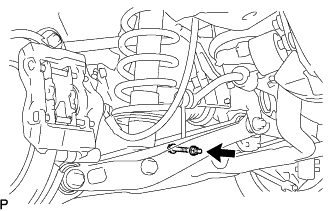

| 3. REMOVE NO. 2 DIFFERENTIAL SUPPORT PROTECTOR |
Remove the 2 nuts and No. 2 differential support protector from the suspension member brace.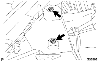
| 4. SEPARATE NO. 3 PARKING BRAKE CABLE ASSEMBLY |
Remove the 2 bolts, and separate the No. 3 parking brake cable.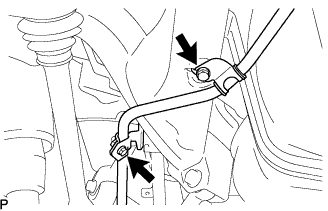
| 5. REMOVE REAR AXLE SHAFT NUT |
Using SST and a hammer, release the staked part of the axle shaft nut.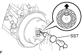
- SST
- 09930-00010
- NOTICE:
- Release the staked part of the nut completely, otherwise the threads of the drive shaft may be damaged.
While depressing the brake pedal, remove the axle shaft nut.
| 6. SEPARATE REAR SPEED SENSOR |
Remove the 2 bolts, and separate the speed sensor from the axle carrier.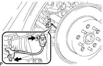
- NOTICE:
- Be careful not to damage the speed sensor.
- Prevent foreign matter from adhering to the speed sensor.
- Be careful not to damage the speed sensor.
| 7. SEPARATE REAR DISC BRAKE CALIPER ASSEMBLY |
Remove the 2 bolts, and disconnect the rear disc brake caliper assembly.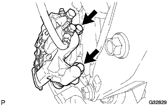
- NOTICE:
- Use wire or equivalent to prevent the brake caliper from hanging down by the flexible hose.
Remove the No.1 caliper plates from the brake caliper.
| 8. REMOVE REAR DISC |
Put matchmarks on the rear disc and the axle hub.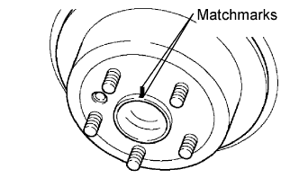
Remove the read disc.
| 9. SEPARATE NO. 2 REAR UPPER CONTROL ARM ASSEMBLY |
Remove the nut from the No. 2 upper control arm assembly rear.
Using SST, separate the No. 2 upper control arm assembly rear from the rear axle carrier sub-assembly.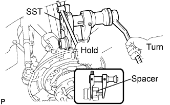
- SST
- 09628-00011
- NOTICE:
- Use caution not to damage the rear axle carrier because it is made of aluminum and may be damaged easily.
- Do not damage the ball joint dust cover.
- Make sure that the SST is securely positioned on the rear axle carrier spacer.
- If the rear axle carrier spacer has come off, replace the rear axle carrier with a new one.
- Make sure that the string of the SST is securely tied to the vehicle.
- Use caution not to damage the rear axle carrier because it is made of aluminum and may be damaged easily.
| 10. SEPARATE NO. 1 REAR UPPER CONTROL ARM ASSEMBLY |
Jack up the rear axle assembly so that the bolt on the No. 1 upper control arm assembly rear can be removed.
- HINT:
- Place a wooden block between the jack and rear axle carrier to prevent damage to the rear axle carrier.
Remove the bolt, washer and nut, and separate the No. 1 upper control arm assembly rear from the rear axle carrier sub-assembly.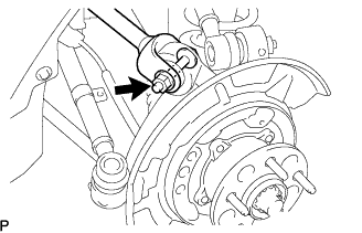
| 11. SEPARATE NO. 1 REAR SUSPENSION ARM ASSEMBLY |
Remove the bolt and nut, and separate the No. 1 rear suspension arm assembly from the rear axle carrier sub-assembly.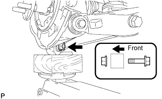
- NOTICE:
- Turn the bolt while holding the nut.
| 12. SEPARATE NO. 2 REAR SUSPENSION ARM ASSEMBLY |
Remove the bolt and nut, and separate the No. 2 rear suspension arm assembly from the rear axle carrier sub-assembly.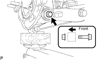
- NOTICE:
- Turn the bolt while holding the nut.
| 13. SEPARATE REAR DRIVE SHAFT ASSEMBLY |
Push the rear axle carrier toward the outside of the vehicle. Using a plastic hammer, separate the rear drive shaft assembly from the rear axle carrier.
- NOTICE:
- Be careful not to damage the joint boot and speed sensor.
- Do not push out the rear axle carrier excessively.
- Use wire or equivalent to prevent the rear drive shaft assembly from hanging down.
- Be careful not to damage the joint boot and speed sensor.
| 14. REMOVE REAR DRIVE SHAFT ASSEMBLY |
Using SST, remove the rear drive shaft assembly.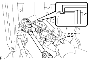
- SST
- 09520-01010
09520-24010 (09520-32040)
- NOTICE:
- Be careful not to damage the oil seal, inboard joint boot and drive shaft dust cover.
- Be careful not to drop the drive shaft assembly.
- Be careful not to damage the oil seal, inboard joint boot and drive shaft dust cover.
| 15. INSPECT REAR DRIVE SHAFT ASSEMBLY |
Check that there is no excessive play in the outboard joint.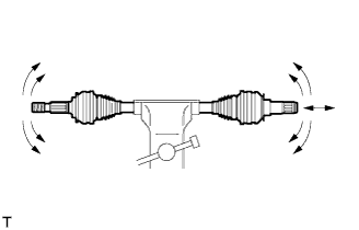
Check that the inboard joint slides smoothly in the thrust direction.
Check that there is no excessive play in the radial directions of the inboard joint.
Check the boot for damage.