DISASSEMBLY
Removal / installation
- CAUTION:
- When working with FIPG material, perform the following:
- Using a razor blade and gasket scraper, remove all the old FIPG material from the gasket surfaces.
- Using a razor blade and gasket scraper, remove all the old FIPG material from the gasket surfaces.
- Thoroughly clean all components to remove any loose material.
- Thoroughly clean all components to remove any loose material.
- Clean both sealing surfaces with a non-residue solvent.
- Clean both sealing surfaces with a non-residue solvent.
- Apply FIPG in a continuous line (width approximately 1 mm (0.04 in.)) along the sealing surface.
- Apply FIPG in a continuous line (width approximately 1 mm (0.04 in.)) along the sealing surface.
- Parts must be assembled within 10 minutes of application. Otherwise, the FIPG material must be removed and reapplied.
- Parts must be assembled within 10 minutes of application. Otherwise, the FIPG material must be removed and reapplied.
| 1. REMOVE TRANSMISSION CASE COVER |

Remove the 2 bolts and the transmission case cover.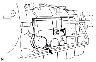

| 2. REMOVE TRANSMISSION CONTROL SHAFT LEVER RH |
Remove the nut, spring washer and the transmission control shaft lever RH.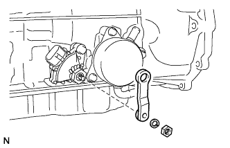
| 3. REMOVE PARK/NEUTRAL POSITION SWITCH ASSEMBLY |
Using a screwdriver, unstake the lock washer.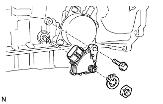
Remove the nut and lock washer.
Remove the bolt and park/neutral position switch.
| 4. REMOVE TRANSMISSION OIL COOLER |
Remove the 3 bolts and transmission oil cooler.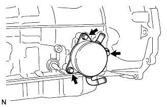
Remove the 2 O-rings from the transmission oil cooler.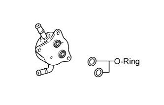
| 5. REMOVE TRANSMISSION REVOLUTION SENSOR |
Remove the 2 bolts and the 2 transmission revolution sensors.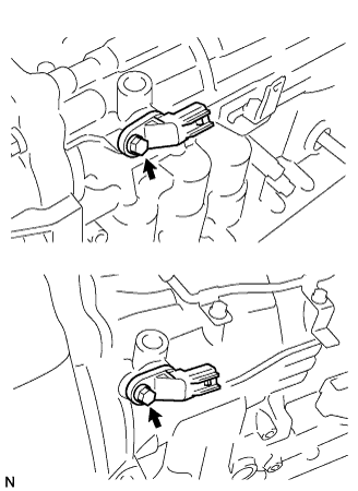
Remove the O-ring from each sensor.
| 6. REMOVE AUTOMATIC TRANSMISSION BREATHER TUBE |
Remove the 2 bolts.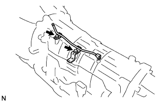
Remove the breather tube.
| 7. REMOVE AUTOMATIC TRANSMISSION HOUSING |
Remove the 10 bolts.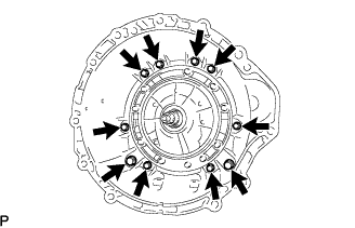
Remove the transmission housing.
| 8. REMOVE EXTENSION HOUSING DUST DEFLECTOR |
Using a brass bar and a hammer, remove the extension housing dust deflector.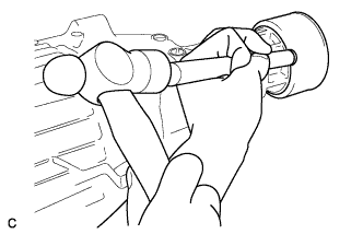
- NOTICE:
- Be careful not to damage the extension housing.
| 9. REMOVE EXTENSION (ATM) HOUSING SUB-ASSEMBLY |
Remove the 6 bolts.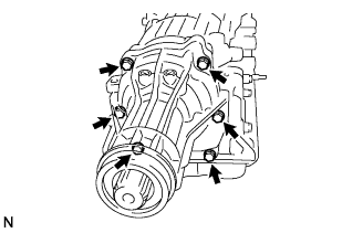
Using a screwdriver, remove the extension housing sub-assembly.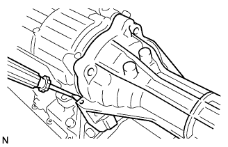
Using a snap ring pliers, remove the snap ring from the extension housing sub-assembly.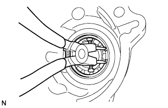
Remove the transmission case adaptor radial ball bearing.
Using a snap ring expander, remove the snap ring.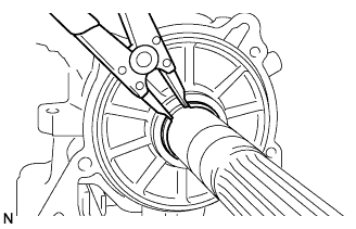
Remove the thrust needle roller bearing and the 2 thrust bearing races.
| 10. REMOVE AUTOMATIC TRANSMISSION EXTENSION HOUSING OIL SEAL |
Using a screwdriver, remove the oil seal.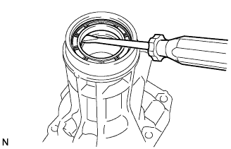
| 11. FIX AUTOMATIC TRANSMISSION CASE SUB-ASSEMBLY |
Install the transmission case on the overhaul attachment.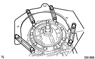
| 12. REMOVE AUTOMATIC TRANSMISSION OIL PAN SUB-ASSEMBLY |
- NOTICE:
- Do not turn the transmission over as this will contaminate the valve body with foreign matter located at the bottom of the pan.
Remove the overflow plug and the gasket.
Remove the drain plug and the gasket.
Remove the 20 bolts, oil pan and gasket.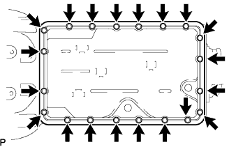
Examine particles in the pan.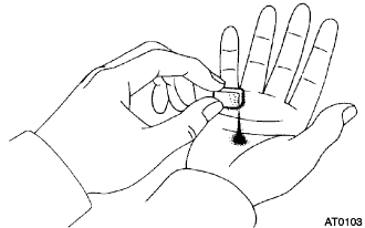
Remove the magnets from the oil pan and use them to collect any steel chips. Look carefully for the chips and particles in the pan and on the magnet to anticipate the type of wear which might be found in the transaxle.
Steel (magnetic): bearing, gear, and plate wear
Brass (non-magnetic): bearing wear
| 13. REMOVE VALVE BODY OIL STRAINER ASSEMBLY |
Turn over the transmission.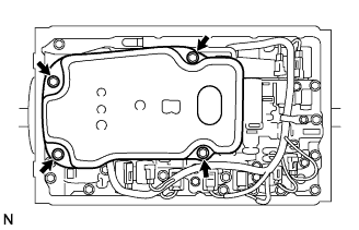
Remove the 4 bolts and valve body oil strainer assembly from the valve body.
Remove the O-ring from the valve body oil strainer assembly.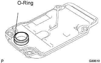
| 14. REMOVE TRANSMISSION WIRE |
Remove the bolt and temperature sensor clamp, and separate the ATF temperature sensor.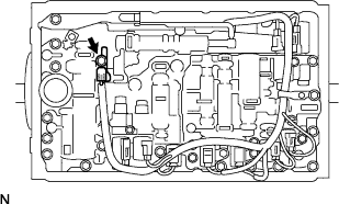
Remove the 2 bolts and disconnect the 2 clamps.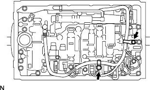
Disconnect the 9 connectors from the solenoid valves.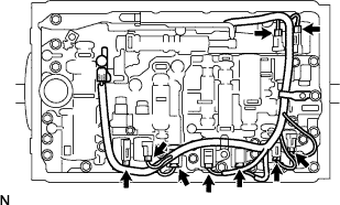
Pull the transmission wire out of the transmission case.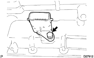
Remove the O-ring from the transmission wire.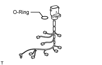
| 15. REMOVE TRANSMISSION VALVE BODY ASSEMBLY |
Remove the bolt, detente spring cover and detente spring.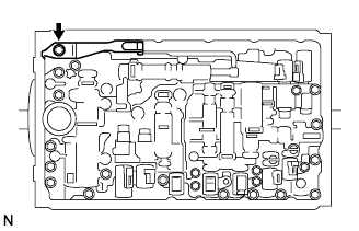
Remove the 19 bolts.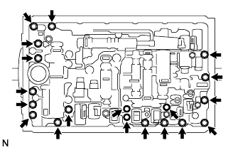
Remove the valve body assembly.
| 16. REMOVE TRANSAXLE CASE GASKET |
Remove the 3 transaxle case gaskets.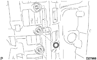
| 17. REMOVE BRAKE DRUM GASKET |
Remove the 3 brake drum gaskets.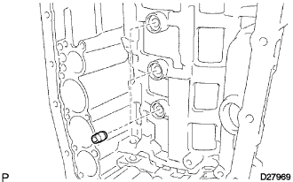
| 18. REMOVE CHECK BALL BODY |
Remove the check ball body and the spring.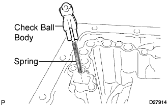
| 19. REMOVE C-2 ACCUMULATOR PISTON |
While blowing compressed air into the oil hole, remove the C-2 accumulator piston and the spring.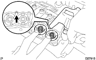
Remove the 2 O-rings from the piston.
- NOTICE:
- Take care as the C-3 and B-3 accumulator pistons may jump out.
| 20. REMOVE B-3 ACCUMULATOR PISTON |
Applying compressed air to the oil hole, remove the B-3 accumulator piston and the spring.
Remove the 2 O-rings from the piston.
- NOTICE:
- Take care as the C-3 accumulator piston may jump out.
| 21. REMOVE C-3 ACCUMULATOR PISTON |
While blowing compressed air into the oil hole, remove the C-3 accumulator piston and the 2 springs.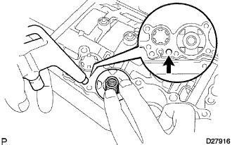
Remove the 2 O-rings from the piston.
| 22. REMOVE B-1 ACCUMULATOR VALVE |
Remove the B-1 accumulator valve and the spring.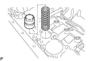
| 23. REMOVE PARKING LOCK PAWL BRACKET |
Remove the 3 bolts and the parking lock pawl bracket.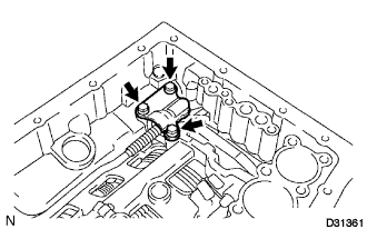
| 24. REMOVE PARKING LOCK ROD SUB-ASSEMBLY |
Disconnect the parking lock rod from the manual valve lever.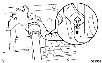
| 25. REMOVE PARKING LOCK PAWL SHAFT |
Pull out the parking lock pawl shaft from the front side, then remove the lock pawl and the spring.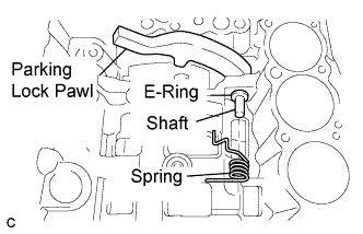
Remove the E-ring from the shaft.
| 26. REMOVE MANUAL VALVE LEVER SUB-ASSEMBLY |
Using a hammer and a screwdriver, cut off the spacer and remove it from the shaft.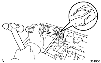
Using a pin punch and a hammer, drive out the spring pin.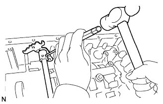
- HINT:
- Slowly drive out the spring pin so that it does not fall into the transmission case.
Pull the manual valve lever shaft out through the case and remove the manual valve lever.
| 27. REMOVE MANUAL VALVE LEVER SHAFT OIL SEAL |
Using a screwdriver, remove the 2 oil seals.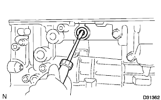
| 28. REMOVE OIL PUMP ASSEMBLY |
Remove the 9 bolts from the transmission case.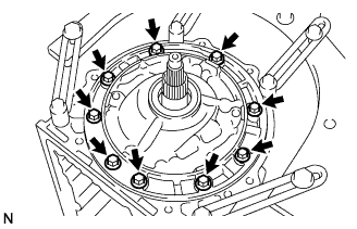
Using a screwdriver with its tip wrapped with tape, pull out the oil pump.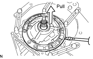
- NOTICE:
- Do not damage the oil pump.
Remove the No. 1 thrust bearing race from the oil pump.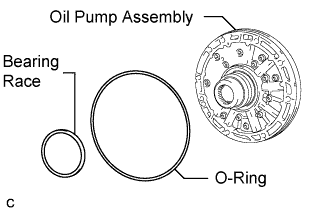
Remove the O-ring from the oil pump.
| 29. REMOVE CLUTCH DRUM AND INPUT SHAFT |
Remove the clutch drum and input shaft from the transmission case.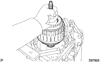
Remove the clutch drum thrust washer, 2 thrust needle roller bearings and bearing race.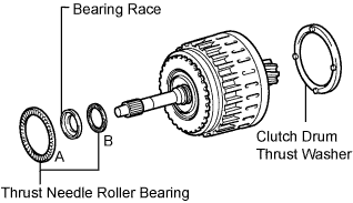
| 30. INSPECT NO. 2 ONE WAY CLUTCH ASSEMBLY |
Hold the reverse clutch hub and turn the No. 2 one way clutch assembly.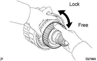
Check that the No. 2 one way clutch assembly turns freely clockwise and locks counterclockwise.
If there is a problem with the one way clutch, replace the one way clutch.
| 31. REMOVE NO. 2 ONE WAY CLUTCH ASSEMBLY |
Remove the No. 2 one way clutch assembly and clutch drum thrust washer from the clutch drum and input shaft.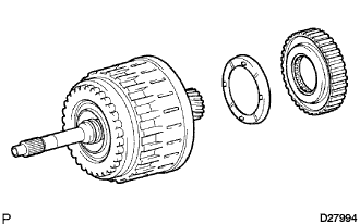
| 32. REMOVE NO. 3 BRAKE SNAP RING |
Using a screwdriver, remove the No. 3 brake snap ring from the transmission case.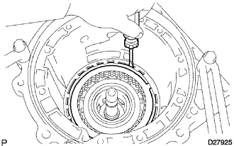
| 33. REMOVE 2ND BRAKE DISC SET |
Remove the flange, 3 discs and 3 plates from the transmission case.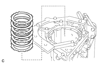
| 34. INSPECT 2ND BRAKE DISC SET |
Check whether the sliding surfaces of the discs, the plates, or the flange are worn or burnt.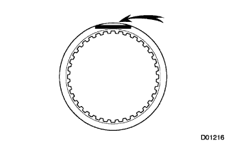
If necessary, replace them.- NOTICE:
- If the linings of the discs are peeled off or discolored, or if any part of the printed numbers is damaged, replace all discs.
- Before assembling new discs, soak them in ATF for at least 15 minutes.
- If the linings of the discs are peeled off or discolored, or if any part of the printed numbers is damaged, replace all discs.
| 35. REMOVE 2ND BRAKE PISTON HOLE SNAP RING |
Using SST, remove the snap ring.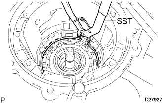
- SST
- 09350-30020
(09350-07060)
| 36. REMOVE ONE WAY CLUTCH ASSEMBLY |
Remove the one way clutch assembly and the No. 1 planetary carrier thrust washer from the transmission case.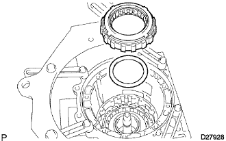
| 37. REMOVE 2ND BRAKE CYLINDER |
Remove the 2nd brake cylinder from the transmission case.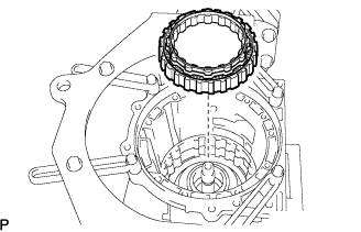
| 38. REMOVE FRONT PLANETARY GEAR ASSEMBLY |
Remove the front planetary gear assembly and the one way clutch inner race from the transmission case.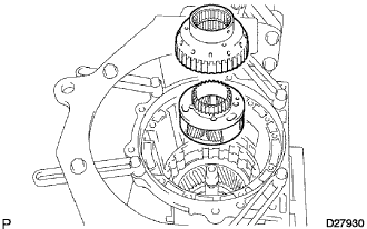
Remove the thrust needle roller bearing, the No. 3 thrust bearing race and the No. 2 planetary carrier thrust washer from the transmission case.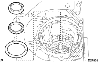
| 39. INSPECT FRONT PLANETARY GEAR ASSEMBLY |
Using a feeler gauge, measure the front planetary pinion gear thrust clearance.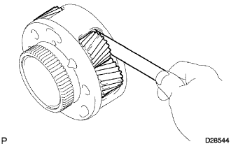
- Standard clearance:
- 0.20 to 0.60 mm (0.008 to 0.024 in.)
Using a dial indicator, measure the inside diameter of the front planetary gear bushing.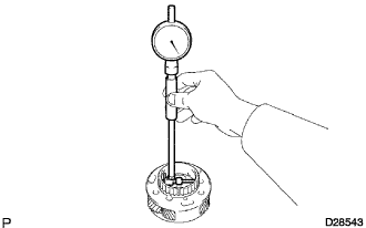
- Standard inside diameter:
- 48.78 mm (1.9205 in.)
| 40. INSPECT ONE WAY CLUTCH ASSEMBLY |
Install the one way clutch assembly to the one way clutch inner race.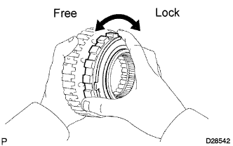
Hold the one way clutch inner race and turn the one way clutch assembly.
Check that the one way clutch assembly turns freely counterclockwise and locks clockwise.
If there is a problem with the one way clutch, replace the one way clutch.
Remove the one way clutch assembly from the one way clutch inner race.
| 41. REMOVE FRONT PLANETARY RING GEAR |
Remove the front planetary ring gear from the transmission case.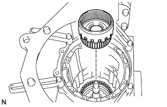
| 42. REMOVE CENTER PLANETARY RING GEAR |
Using a screwdriver, remove the snap ring.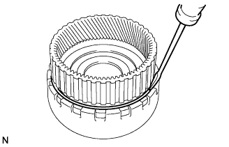
Remove the center planetary ring gear from the front planetary ring gear.
Using a screwdriver, remove the snap ring.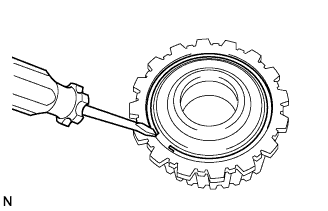
Remove the center planetary ring gear flange from the center planetary ring gear.
Remove the thrust needle roller bearing from the front planetary ring gear flange.
| 43. REMOVE NO. 1 BRAKE DISC |
Remove the flange, the 3 discs and the 3 plates from the transmission case.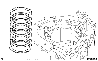
| 44. INSPECT NO. 1 BRAKE DISC |
Check whether the sliding surfaces of the discs, the plates, or the flange are worn or burnt.
If necessary, replace them.- NOTICE:
- If the linings of the discs are peeled off or discolored, or if any part of the groove is damaged, replace all discs.
- Before assembling new discs, soak them in ATF for at least 15 minutes.
- If the linings of the discs are peeled off or discolored, or if any part of the groove is damaged, replace all discs.
| 45. REMOVE BRAKE PISTON RETURN SPRING SNAP RING |
Using a screwdriver, remove the brake piston return spring snap ring from the transmission case.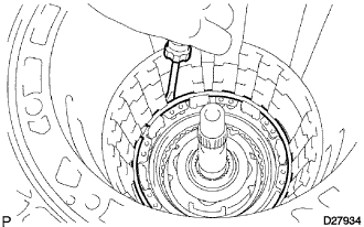
| 46. REMOVE BRAKE PISTON RETURN SPRING SUB-ASSEMBLY |
Remove the brake piston return spring, the No. 1 brake piston and the No. 1 brake cylinder from the transmission case.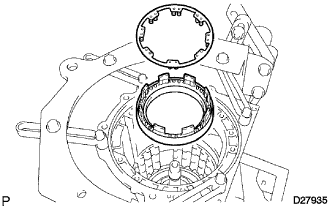
| 47. INSPECT BRAKE PISTON RETURN SPRING SUB-ASSEMBLY |
Using vernier calipers, measure the free length of the spring together with the spring seat.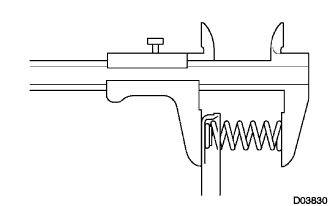
- Standard free length:
- 17.05 mm (0.671 in.)
| 48. REMOVE NO. 1 BRAKE PISTON |
Hold the No. 1 brake cylinder and apply compressed air (392 kPa, 4 kgf/cm2, 57 psi) to the No. 1 brake cylinder to remove the No. 1 brake piston.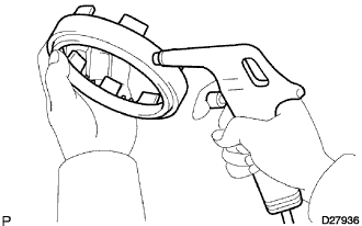
- HINT:
- If the piston does not pop out with compressed air, lift the piston out with needle-nose pliers.
Remove the 2 O-rings from the No. 1 brake piston.
| 49. REMOVE NO. 2 BRAKE DISC |
Using a screwdriver, remove the snap ring from the transmission case.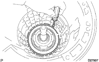
Remove the 2 flanges, the brake piston return spring, the 4 discs and the 3 plates from the transmission case.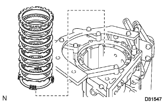
| 50. INSPECT NO. 2 BRAKE DISC |
Check whether the sliding surfaces of the discs, the plates, and the flange are worn or burnt.
If necessary, replace them.- NOTICE:
- If the linings of the discs are peeled off or discolored, or if any part of the printed numbers is damaged, replace all discs.
- Before assembling new discs, soak them in ATF for at least 15 minutes.
- If the linings of the discs are peeled off or discolored, or if any part of the printed numbers is damaged, replace all discs.
| 51. INSPECT NO. 2 BRAKE PISTON RETURN SPRING SUB-ASSEMBLY |
Using vernier calipers, measure the free length of the spring together with the spring seat.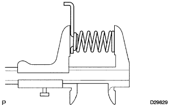
- Standard free length:
- 22.66 mm (0.8921 in.)
| 52. REMOVE NO. 2 BRAKE PISTON |
Hold the No. 2 brake piston and apply compressed air (392 kPa, 4 kgf/cm2, 57 psi) to the transmission case to remove the No. 2 brake piston and the No. 2 brake cylinder.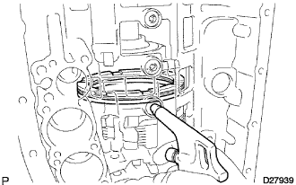
- HINT:
- If the piston does not pop out with compressed air, lift the piston out with needle-nose pliers.
Remove the piston from the cylinder.
Remove the 2 O-rings from the No. 2 brake piston.
| 53. REMOVE CENTER PLANETARY GEAR ASSEMBLY |
Remove the center planetary gear assembly, the planetary sun gear and the No. 4 thrust bearing race from the transmission case.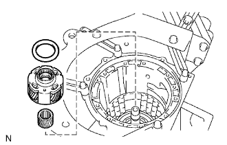
| 54. INSPECT CENTER PLANETARY GEAR ASSEMBLY |
Using a feeler gauge, measure the center planetary gear pinion thrust clearance.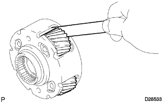
- Standard clearance:
- 0.12 to 0.68 mm (0.005 to 0.027 in.)
| 55. REMOVE INTERMEDIATE SHAFT |
Using SST, remove the snap ring from the transmission case.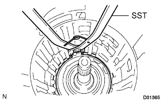
- SST
- 09350-30020
(09350-07060)
Remove the intermediate shaft with the No. 3 one way clutch assembly from the transmission case.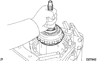
| 56. INSPECT NO. 3 ONE WAY CLUTCH ASSEMBLY |
Hold the rear planetary ring gear flange sub-assembly and turn the one way clutch assembly.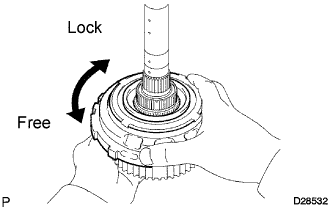
Check that the one way clutch assembly turns freely counterclockwise and locks clockwise.
If there is a problem with the one way clutch, replace the one way clutch.
| 57. REMOVE NO. 3 ONE WAY CLUTCH ASSEMBLY |
Remove the No. 3 one way clutch assembly and the one way clutch inner race from the intermediate shaft.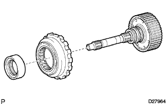
| 58. REMOVE REAR PLANETARY RING GEAR FLANGE SUB-ASSEMBLY |
Remove the No. 8 thrust bearing race, the thrust needle roller bearing, the No. 7 thrust bearing race and the planetary ring gear flange from the intermediate shaft.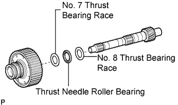
| 59. INSPECT INTERMEDIATE SHAFT |
Using a dial indicator, check the intermediate shaft runout.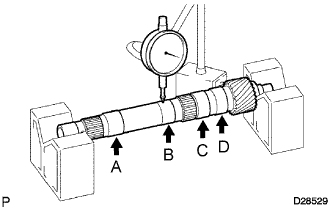
- Standard runout:
- A:
- 0.03 mm (0.0012 in.)
- B:
- 0.03 mm (0.0012 in.)
- C:
- 0.03 mm (0.0012 in.)
- D:
- 0.03 mm (0.0012 in.)
Using a micrometer, check the outer diameter of the intermediate shaft at each point shown in the illustration.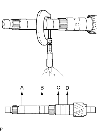
- Standard diameter:
- A:
- 22.962 to 22.975 mm (0.904 to 0.905 in.)
- B:
- 22.962 to 22.975 mm (0.904 to 0.905 in.)
- C:
- 27.759 to 27.775 mm (1.0929 to 1.0935 in.)
- D:
- 27.759 to 27.775 mm (1.0929 to 1.0935 in.)
| 60. REMOVE BRAKE PLATE STOPPER SPRING |
Remove the brake plate stopper spring from the transmission case.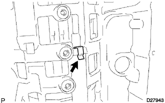
| 61. REMOVE NO. 4 BRAKE DISC |
Remove the 4 plates, 5 discs and 2 flanges from the transmission case.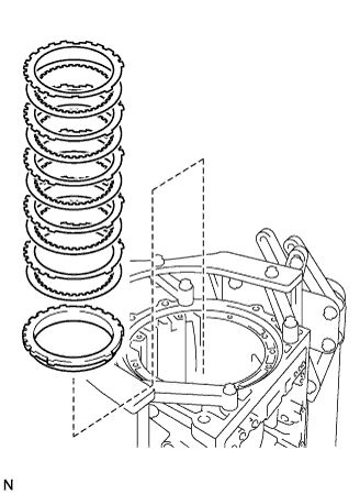
| 62. INSPECT NO. 4 BRAKE DISC |
Check whether the sliding surfaces of the discs, the plates, and the flanges are worn or burnt.
If necessary, replace them.- NOTICE:
- If the linings of the discs are peeled off or discolored, or if any part of the printed numbers is damaged, replace all discs.
- Before assembling new discs, soak them in ATF for at least 15 minutes.
- If the linings of the discs are peeled off or discolored, or if any part of the printed numbers is damaged, replace all discs.
| 63. REMOVE REAR PLANETARY GEAR ASSEMBLY |
Remove the rear planetary gear assembly from the transmission case.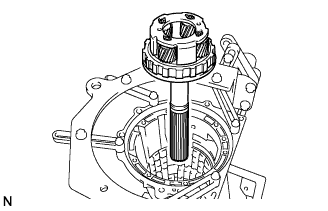
Remove the No. 9 thrust bearing race, thrust bearing race and the thrust needle roller bearing from the rear planetary gear assembly.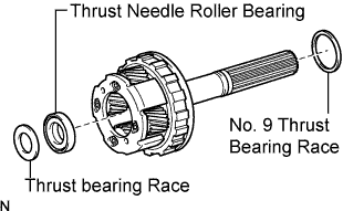
Remove the thrust needle roller bearing from the transmission case.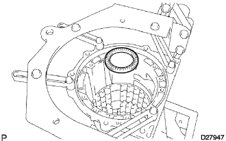
| 64. INSPECT REAR PLANETARY GEAR ASSEMBLY |
Using a feeler gauge, measure the rear planetary gear pinion thrust clearance.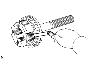
- Standard clearance:
- 0.2 to 0.6 mm (0.008 to 0.024 in.)
Using a dial indicator, measure the inside diameter of the rear planetary gear bushing.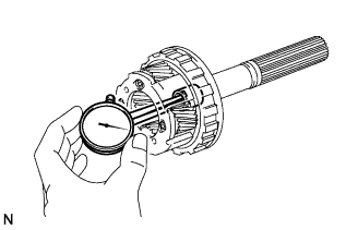
- Standard inside diameter:
- 18.025 mm (0.710 in.)
| 65. REMOVE 1ST AND REVERSE BRAKE RETURN SPRING SUB-ASSEMBLY |
Place SST on the 1st and reverse brake return spring sub-assembly and compress the brake return spring.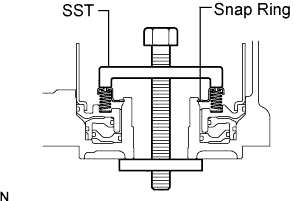
- SST
- 09350-30020
(09350-07050)
Using the SST, remove the snap ring and the brake return spring.
- SST
- 09350-30020
(09350-07070)
| 66. INSPECT 1ST AND REVERSE BRAKE RETURN SPRING SUB-ASSEMBLY |
Using vernier calipers, measure the free length of the spring together with the spring seat.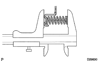
- Standard free length:
- 23.74 mm (0.94 in.)
| 67. REMOVE BRAKE APPLY TUBE |
Remove the brake apply tube from the 1st and reverse brake piston.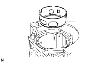
| 68. REMOVE 1ST AND REVERSE BRAKE PISTON |
Hold the 1st and reverse brake piston and blow compressed air (392 kPa, 4 kgf/cm2, 57 psi) into the transmission case to remove the brake piston.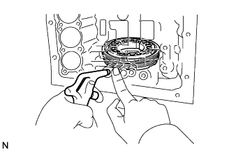
- HINT:
- If the piston does not pop out with compressed air, lift the piston out with needle-nose pliers.
Remove the brake apply tube from the piston.
Remove the O-ring from the brake piston.
| 69. REMOVE BRAKE REACTION SLEEVE |
Using SST, remove the reaction sleeve.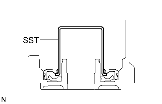
- SST
- 09350-30020
(09350-07080)
Remove the 2 O-rings from the reaction sleeve.
| 70. REMOVE NO. 4 BRAKE PISTON |
Using SST, remove the No. 4 brake piston.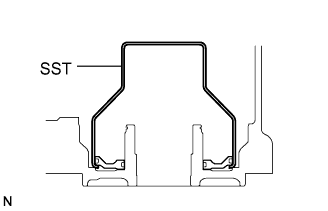
- SST
- 09350-30020
(09350-07080)
Remove the 2 O-rings from the No. 4 brake piston.