REASSEMBLY
Removal / installation
| 1. BEARING POSITION |

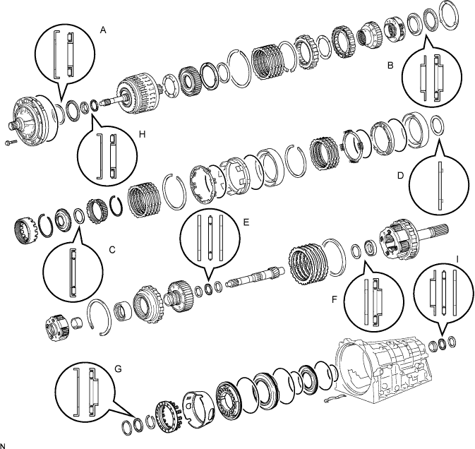

| Mark |
Front Race Diameter Inside/Outside |
Thrust Bearing Diameter Inside/Outside |
Rear Race Diameter Inside/Outside |
| A |
74.2 mm (2.921 in.) /87.7 mm (3.453 in.) |
71.9 mm (2.831 in.) /85.6 mm (3.370 in.) |
- |
| B |
34.9 mm (1.374 in.) /50.8 mm (2.0 in.) |
38.6 mm (1.520 in.) /53.1 mm (2.091 in.) |
- |
| C |
- |
58.5 mm (2.303 in.) /73.5 mm (2.894 in.) |
- |
| D |
- |
- |
55.2 mm (2.173 in.) /71.2 mm (2.803 in.) |
| E |
29.6 mm (1.165 in.) /44.9 mm (1.768 in.) |
27.8 mm (1.095 in.) /43.85 mm (1.726 in.) |
27.8 mm (1.095 in.) /43.7 mm (1.721 in.) |
| F |
19.0 mm (0.748 in.) /35.0 mm (1.378 in.) |
20.8 mm (0.819 in.) /38.5 mm (1.516 in.) |
- |
| G |
43.3 mm (1.705 in.) /56.7 mm (2.232 in.) |
40.6 mm (1.598 in.) /58.0 mm (2.284 in.) |
- |
| H |
37.0 mm (1.457 in.) /51.2 mm (2.016 in.) |
33.5 mm (1.319 in.) /48.0 mm (1.890 in.) |
- |
| I |
37.0 mm (1.457 in.) /51.2 mm (2.016 in.) |
36.1 mm (1.421 in.) /52.5 mm (2.067 in.) |
36.1 mm (1.421 in.) /51.0 mm (2.007 in.) |
| 2. INSTALL NO. 4 BRAKE PISTON |
Coat 2 new O-rings with ATF, and install them to the brake reaction sleeve.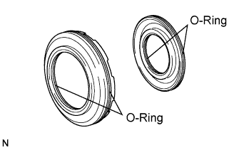
Coat 2 new O-rings with ATF, and install them to the No. 4 brake piston.
Install the No. 4 brake piston to the reaction sleeve.
- NOTICE:
- Be careful not to damage the 4 O-rings.
| 3. INSTALL BRAKE REACTION SLEEVE |
With the No. 4 brake piston underneath (the rear side), install the brake reaction sleeve and the No. 4 brake piston to the transmission case.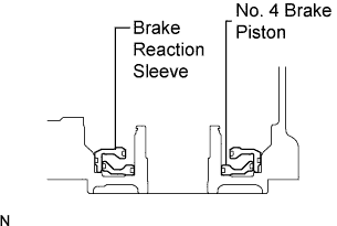
- NOTICE:
- Be careful not to damage the O-rings.
| 4. INSTALL 1ST AND REVERSE BRAKE PISTON |
Coat a new O-ring with ATF.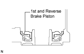
Install the O-ring on the 1st and reverse brake piston.
With the spring seat of the piston facing upwards (the front side), place the piston in the transmission case.
- NOTICE:
- Be careful not to damage the O-ring.
| 5. INSTALL 1ST AND REVERSE BRAKE RETURN SPRING SUB-ASSEMBLY |
Place the brake return spring onto the brake piston.
Place SST on the brake return spring, and compress the return spring.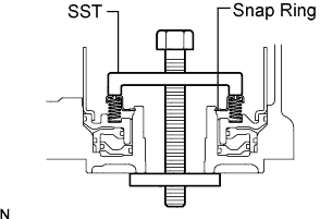
- SST
- 09350-30020
(09350-07050)
Using the SST, install the snap ring.
- SST
- 09350-30020
(09350-07070)
| 6. INSTALL BRAKE APPLY TUBE |
Install the brake apply tube with its protruding part fitting into the groove of the transmission case as shown in the illustration.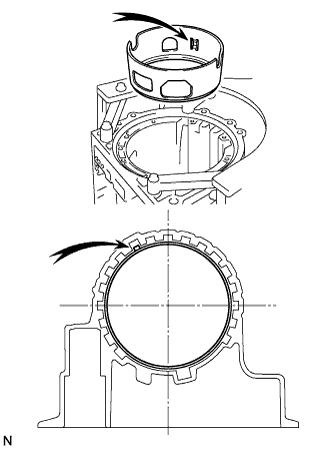
| 7. INSTALL REAR PLANETARY GEAR ASSEMBLY |
Install the thrust needle roller bearing.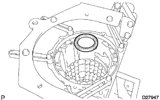
- Thrust needle roller bearing diameter:
Inside
Outside
Thrust needle roller bearing
40.6 mm (1.598 in.)
58.0 mm (2.284 in.)
Install the thrust needle roller bearing.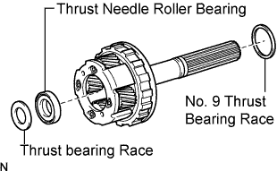
Coat the No. 9 thrust bearing race and thrust bearing race with petroleum jelly, and install them onto the rear planetary gear.
- Bearing and race diameter:
Inside
Outside
Bearing
20.8 mm (0.819 in.)
38.5 mm (1.516 in.)
Thrust bearing Race
19.0 mm (0.748 in.)
35.0 mm (1.378 in.)
No. 9 thrust bearing Race
43.3 mm (1.705 in.)
56.7 mm (2.232 in.)
Install the rear planetary gear assembly.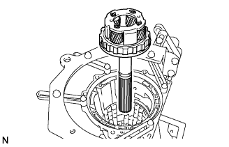
| 8. INSPECT PACK CLEARANCE OF 1ST AND REVERSE BRAKE |
Make sure that the 1st and reverse brake piston moves smoothly when pulling and releasing the compressed air gun lever while applying compressed air into the transmission case.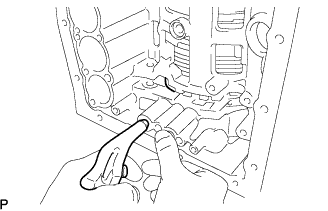
Using vernier calipers, measure the level difference (dimension A) between the upper surface of the brake apply tube and the hitting surface of the No. 4 brake flange at both ends across the 1st and reverse brake piston diameter, and calculate the average.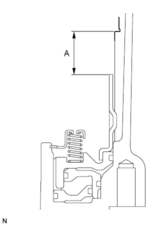
- NOTICE:
- The 1st and reverse brake piston must be securely installed to the end face of the transmission case.
- HINT:
- Dimension A = 23.32 to 24.18 mm (0.9181 to 0.952 in.)
Using vernier calipers, measure the thickness (dimension B) of the brake flanges, the 4 No. 4 brake plates and the 5 No. 4 brake discs altogether the both ends across a diameter, and calculate the average.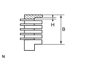
- HINT:
- Dimension B = 23.64 to 26.00 mm (0.9307 to 1.0236 in.)
- Pack Clearance = Dimension A - Dimension B - 0.18 mm (0.0071 in.) + 1.8 mm (0.071 in.)
- Pack Clearance:
- 0.5 to 0.8 mm (0.0197 to 0.0315 in.)
If the pack clearance is outside the standard range, select and install a brake flange that brings the pack clearance to be within the standard range.
- HINT:
- There are 8 types of flanges that can be used to adjust the pack clearance. Select the one with the most appropriate thickness.
- Thickness H:
NO.
Thickness H
NO.
Thickness H
0
0 mm (0 in.)
8
0.8 mm (0.03150 in.)
2
0.2 mm (0.00787 in.)
10
1.0 mm (0.03937 in.)
4
0.4 mm (0.01575 in.)
12
1.2 mm (0.04724 in.)
6
0.6 mm (0.02362 in.)
14
1.4 mm (0.05512 in.)
| 9. INSTALL NO. 4 BRAKE DISC |
Install the 4 plates, the 5 discs and the 2 flanges.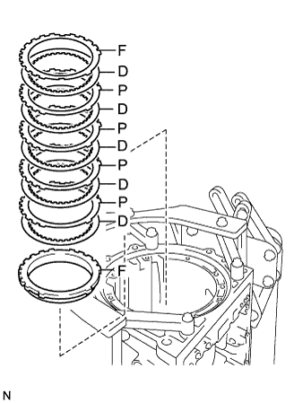
- Install in order:
- P = Plate, D = Disc, F = Flange
- F - D - P - D - P - D - P - D - P - D - F
| 10. INSTALL BRAKE PLATE STOPPER SPRING |
Install the brake plate stopper spring.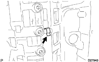
| 11. INSTALL REAR PLANETARY RING GEAR FLANGE SUB-ASSEMBLY |
Install the No. 8 thrust bearing race, the thrust needle roller bearing, the No. 7 thrust bearing race and the planetary ring gear flange to the intermediate shaft.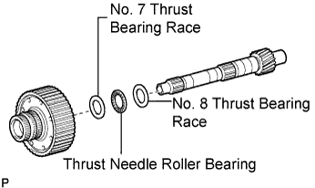
- Bearing and race diameter:
Inside
Outside
No. 7 thrust bearing race
29.6 mm (1.165 in.)
44.9 mm (1.768 in.)
Thrust needle roller bearing
27.8 mm (1.095 in.)
43.85 mm (1.726 in.)
No. 8 thrust bearing race
27.8 mm (1.095 in.)
43.7 mm (1.721 in.)
| 12. INSTALL NO. 3 ONE WAY CLUTCH ASSEMBLY |
Install the No. 3 one way clutch assembly and the one way clutch inner race to the intermediate shaft.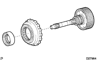
| 13. INSTALL INTERMEDIATE SHAFT |
Install the intermediate shaft with the No. 3 one way clutch assembly to the case.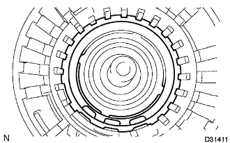
Using SST, install the snap ring.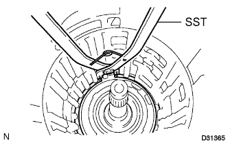
- SST
- 09350-30020
(09350-07050, 09350-07060)
| 14. INSTALL CENTER PLANETARY GEAR ASSEMBLY |
Install the center planetary gear assembly and the planetary sun gear to the case.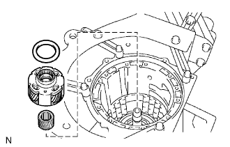
Coat the thrust bearing race with petroleum jelly, and install it onto the center planetary gear assembly.
- Race diameter:
Inside
Outside
Race
55.2 mm (2.173 in.)
71.2 mm (2.803 in.)
| 15. INSTALL NO. 2 BRAKE PISTON |
Coat 2 new O-rings with ATF, and install them to the No. 2 brake piston.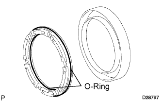
Press the No. 2 brake piston into the No. 2 brake cylinder.
- NOTICE:
- Be careful not to damage the 2 O-rings.
Install the No. 2 brake piston to the case.
- HINT:
- Install the No. 2 brake cylinder so that the projection protrudes from the upside of the transmission case.
Check that the oil pressure apply hole of the No. 2 brake cylinder aligns with the oil pressure apply hole of the transmission case.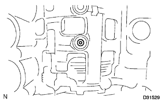
| 16. INSTALL NO. 2 BRAKE DISC |
Install the 2 flanges, 3 plates, 4 discs and brake piston return spring.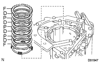
- Install in order:
- P = Plate, D = Disc, F = Flange
- F -D - P - D - P - D - P - D - F
Using SST, a screwdriver and a press, install the No. 2 brake spring snap ring.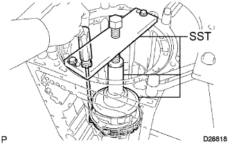
- SST
- 09351-40010
(09351-04010, 09351-04020, 09351-04040, 09351-04050)
| 17. INSPECT PISTON STROKE OF NO. 2 BRAKE PISTON |
Inspect piston stroke of the No. 2 brake piston.
Make sure that the No. 2 brake piston moves smoothly when pulling and releasing the compressed air gun lever while applying compressed air into the transmission case.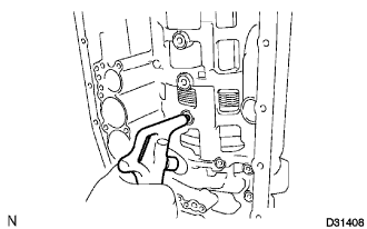
Using SST and a dial indicator, measure the moving distance (dimension A) of the clutch disc at both ends across a diameter while blowing air from the oil hole as shown in the illustration, and calculate the average.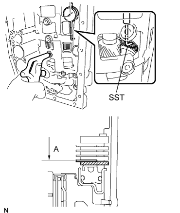
- SST
- 09350-30020
(09350-06120)
- Piston stroke:
- 0.6 to 0.9 mm (0.024 to 0.035 in.)
If the piston stroke is outside the standard range, select and install a brake flange that brings the piston stroke within the standard range.
- HINT:
- There are 8 types of flanges that can be used to adjust the piston stroke. Select one with the most appropriate thickness.
- Flange thickness:
No.
Thickness
0
2.0 mm (0.079 in.)
1
2.1 mm (0.083 in.)
2
2.2 mm (0.087 in.)
3
2.3 mm (0.091 in.)
4
2.4 mm (0.094 in.)
5
2.5 mm (0.098 in.)
6
2.6 mm (0.102 in.)
7
2.7 mm (0.106 in.)
| 18. INSTALL NO. 1 BRAKE PISTON |
Coat 2 new O-rings with ATF, and install them on the No. 1 brake piston.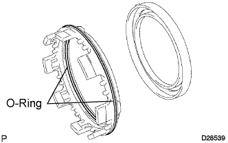
Press the No. 1 brake piston into the No. 1 brake cylinder.
- NOTICE:
- Be careful not to damage the 2 O-rings.
| 19. INSTALL BRAKE PISTON RETURN SPRING SUB-ASSEMBLY |
Install the brake piston return spring and the No. 1 brake piston with the No. 1 brake cylinder to the transmission case.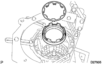
- HINT:
- Install the No. 1 brake cylinder so that the projection protrudes from the upside of the transmission case.
Check that the oil pressure apply hole of the No. 2 brake cylinder aligns with the oil pressure apply hole of the transmission case.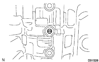
| 20. INSTALL BRAKE PISTON RETURN SPRING SNAP RING |
Using SST, a screwdriver and a press, install the brake piston return spring snap ring.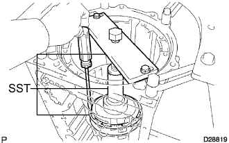
- SST
- 09351-40010
(09351-04010, 09351-04030, 09351-04040, 09351-04050)
| 21. INSTALL CENTER PLANETARY RING GEAR |
Install the thrust needle roller bearing to the front planetary ring gear flange.
- Thrust needle roller bearing diameter:
Inside
Outside
Thrust needle roller bearing
58.5 mm (2.303 in.)
73.5 mm (2.894 in.)
Install the center planetary ring gear flange to the center planetary ring gear.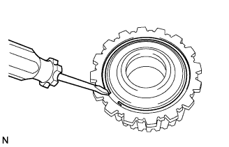
Using a screwdriver, install the snap ring.
Install the center planetary ring gear to the front planetary ring gear.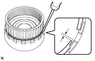
Using a screwdriver, install the snap ring.
- NOTICE:
- Install the snap ring to the ring gear so that the both ends of the snap ring come to the center of a protrusion on the ring gear.
| 22. INSTALL FRONT PLANETARY RING GEAR |
Install the front planetary ring gear to the case.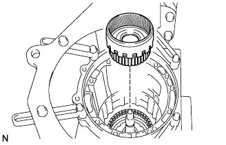
| 23. INSTALL FRONT PLANETARY GEAR ASSEMBLY |
Install the thrust needle roller bearing and the thrust washer.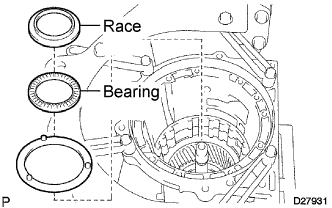
Coat the thrust bearing race with petroleum jelly, and install it onto the front planetary ring gear.
- Thrust needle roller bearing and race diameter:
Inside
Outside
Bearing
38.6 mm (1.520 in.)
53.1 mm (2.091 in.)
Race
34.9 mm (1.374 in.)
50.8 mm (2.0 in.)
Install the front planetary gear assembly and the one way clutch inner race to the case.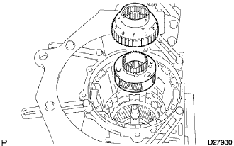
| 24. INSPECT PISTON STROKE OF BRAKE PISTON |
Inspect piston stroke of the No. 1 brake piston.
Make sure the No. 1 brake piston moves smoothly when pulling and releasing the compressed air gun lever while applying compressed air into the transmission case.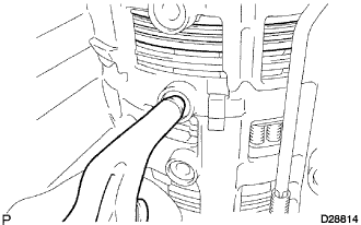
Using vernier calipers, measure the level difference (dimension A) between the upper surface of the No. 1 brake piston and the hitting surface of the No. 1 brake flange at both ends across the No. 1 brake piston diameter.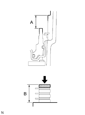
Using vernier calipers, measure the thickness (dimension B) of the brake flange, the No. 1 brake plates and the 3 No. 1 brake discs altogether at the both ends across a diameter, and calculate the average.
- HINT:
- Dimension A = 15.27 to 15.92 mm (0.60118 to 0.62677 in.)
- Dimension B = 14.50 to 15.54 mm (0.57087 to 0.61180 in.)
- Piston stroke = Dimension A - Dimension B
- Piston stroke:
- 0.42 to 0.72 mm (0.017 to 0.028 in.)
If the piston stroke is not still outside the specified range, select another flange that brings the piston stroke within the specified range.- HINT:
- There are 4 different thicknesses for the flange.
- Flange thickness:
No.
Thickness
0
2.0 mm (0.079 in.)
1
2.2 mm (0.087 in.)
2
2.4 mm (0.094 in.)
3
2.6 mm (0.102 in.)
| 25. INSTALL NO. 1 BRAKE DISC |
Install the 3 plates, the 3 discs and the flange.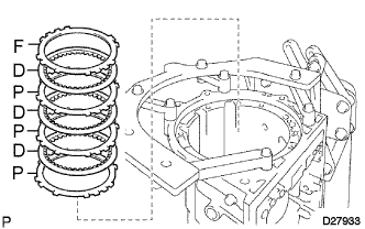
- Install in order:
- P = Plate, D = Disc, F = Flange
- F - D - P - D - P - D - P
| 26. INSTALL 2ND BRAKE CYLINDER |
Install the 2nd brake cylinder to the case.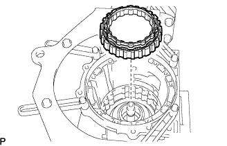
Check that the oil pressure apply hole of the 2nd brake cylinder aligns with the oil pressure apply hole of the transmission case.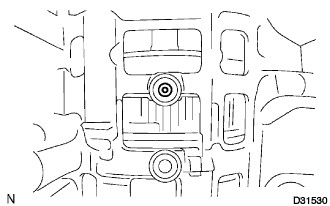
| 27. INSTALL ONE WAY CLUTCH ASSEMBLY |
Install the one way clutch assembly and the thrust washer to the case.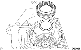
| 28. INSTALL 2ND BRAKE PISTON HOLE SNAP RING |
Using SST, install the snap ring.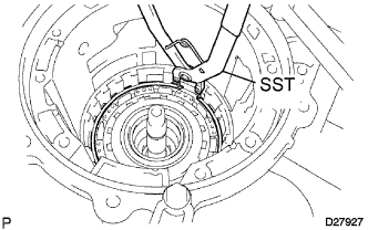
- SST
- 09350-30020
(09350-07060)
| 29. INSTALL 2ND BRAKE DISC SET |
Install the flange, the 3 discs and the 3 plates to the case.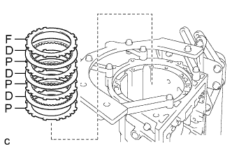
- Install in order:
- P = Plate, D = Disc, F = Flange
- F - D - P - D - P - D - P
| 30. INSTALL NO. 3 BRAKE SNAP RING |
Using a screwdriver, install the snap ring.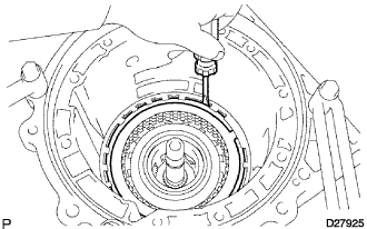
- SST
- 09350-30020
(09350-07060)
| 31. INSTALL NO. 2 ONE WAY CLUTCH ASSEMBLY |
Install the No. 2 one way clutch assembly and No. 2 washer to the clutch drum and input shaft.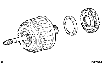
| 32. INSPECT NO. 2 ONE WAY CLUTCH ASSEMBLY |
Hold the reverse clutch hub and turn the No. 2 one way clutch assembly.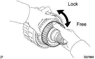
Check that the No. 2 one way clutch assembly turns freely clockwise and locks counterclockwise.
If there is a problem with the one way clutch, replace the one way clutch.
| 33. INSTALL CLUTCH DRUM AND INPUT SHAFT |
Install the 2 thrust needle roller bearings and thrust washer.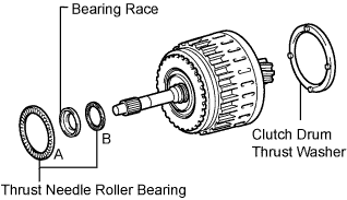
Coat the race and washer with petroleum jelly and install them onto the clutch drum and input shaft assembly.
- Thrust needle roller bearing and diameter:
Inside
Outside
Thrust needle roller bearing A
71.9 mm (2.831 in.)
85.6 mm (3.370 in.)
Bearing Race
37.0 mm (1.457 in.)
51.2 mm (2.016 in.)
Thrust needle roller bearing B
33.5 mm (1.319 in.)
48.0 mm (1.890 in.)
Install the clutch drum and input shaft into the transmission case.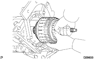
| 34. INSTALL OIL PUMP ASSEMBLY |
Install the No. 1 thrust bearing race to the front oil pump.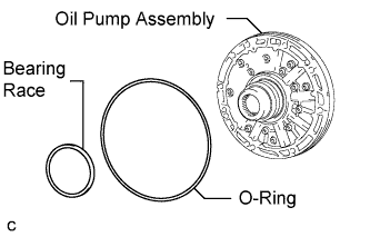
Inside
Outside
Race
74.2 mm (2.921 in.)
87.7 mm (3.453 in.)
Coat a new O-ring with ATF, and install it around the oil pump assembly.
Place the oil pump through the input shaft, and align the bolt holes of the oil pump assembly with the transmission case.
Hold the input shaft, and lightly press the oil pump body to slide the oil seal rings into the overdrive direct clutch drum.
Install the 9 bolts.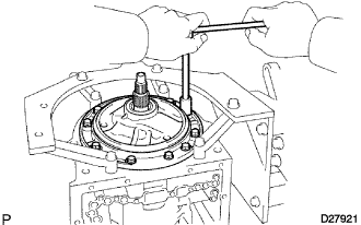
- Torque:
- 21 N*m{ 214 kgf*cm , 15 ft.*lbf }
| 35. INSTALL MANUAL VALVE LEVER SHAFT OIL SEAL |
Using SST and a hammer, drive in 2 new oil seals.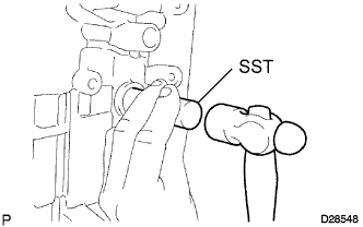
- SST
- 09350-30020
(09350-07110)
Coat the oil seal lips with MP grease.
| 36. INSPECT INDIVIDUAL PISTON OPERATION |
Check the operating sound while applying compressed air into the oil holes indicated in the illustration.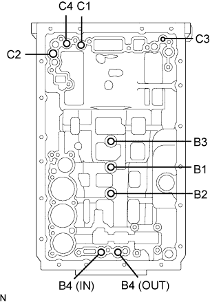
- HINT:
- When inspecting the O/D direct clutch, check the operating sound with the C3 accumulator piston hole closed.
- If there is no sound, disassemble and check the installation condition of the parts.
No. 2 Clutch (C2)
No. 4 Clutch (C4)
No. 3 Clutch (C3)
No. 1 Clutch (C1)
No. 3 Brake (B3)
No. 1 Brake (B1)
No. 2 Brake (B2)
No. 4 Brake (B4)
| 37. INSTALL MANUAL VALVE LEVER SUB-ASSEMBLY |
Install a new spacer to the manual valve lever.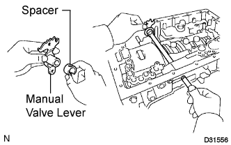
Install the manual valve lever shaft to the transmission case through the manual valve lever.
Using a hammer, drive in a new spring pin.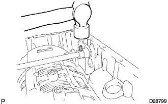
Align the manual valve lever indentation with the spacer hole, and stake them together with the punch.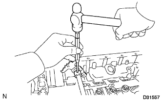
Make sure that the shaft rotates smoothly.
| 38. INSTALL PARKING LOCK PAWL SHAFT |
Install a new E-ring to the shaft.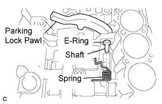
Install a new parking lock pawl, the shaft and the spring.
| 39. INSTALL PARKING LOCK ROD SUB-ASSEMBLY |
Connect the parking lock rod to the manual valve lever.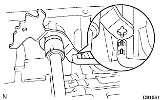
| 40. INSTALL PARKING LOCK PAWL BRACKET |
Place the parking lock pawl bracket onto the transmission case and tighten the 3 bolts.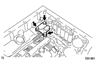
- Torque:
- 7.3 N*m{ 74 kgf*cm , 65 in.*lbf }
Shift the manual valve lever to the P position, and confirm that the planetary gear is correctly locked up by the lock pawl.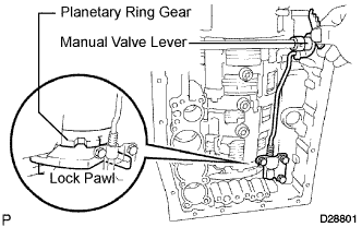
| 41. INSTALL B-1 ACCUMULATOR VALVE |
Install the spring and the accumulator valve to the hole.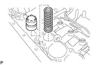
- B-1 accumulator spring:
Free length
Outer diameter
Color
46.36 mm (1.8252 in.)
17.10 mm (0.6732 in.)
Natural
| 42. INSTALL C-3 ACCUMULATOR PISTON |
Coat 2 new O-rings with ATF, and install them to the piston.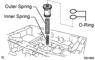
Install the 2 springs and the accumulator piston to the hole.
- C-3 accumulator spring:
Inner spring: Free length
Outer diameter
Color
44.0 mm (1.732 in.)
14.0 mm (0.551 in.)
Yellow
Outer spring: Free length
Outer diameter
Color
76.65 mm (3.0178 in.)
20.10 mm (0.7913 in.)
White
| 43. INSTALL B-3 ACCUMULATOR PISTON |
Coat 2 new O-rings with ATF, and install them to the piston.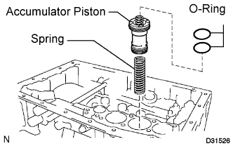
Install the spring and the accumulator piston to the hole.
- Accumulator spring:
Free length
Outer diameter
Color
64.5 mm (2.539 in.)
19.5 mm (0.768 in.)
Orange
| 44. INSTALL C-2 ACCUMULATOR PISTON |
Coat 2 new O-rings with ATF, and install them to the piston.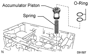
Install the spring and the accumulator piston to the hole.
- Accumulator spring:
Free length
Outer diameter
Color
65.07 mm (2.5618 in.)
16.2 mm (0.6378 in.)
Pink
| 45. INSTALL CHECK BALL BODY |
Install the check ball body and the spring.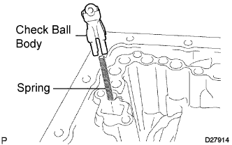
| 46. INSTALL BRAKE DRUM GASKET |
Install the 3 new brake drum gaskets.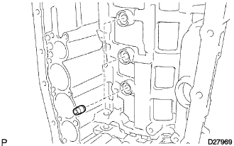
| 47. INSTALL TRANSAXLE CASE GASKET |
Install the 3 new transaxle case gaskets.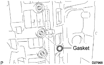
| 48. INSTALL TRANSMISSION VALVE BODY ASSEMBLY |
Align the groove of the manual valve lever with the pin of the manual valve.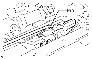
Install the 19 bolts.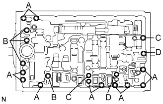
- Torque:
- 11 N*m{ 110 kgf*cm , 8 ft.*lbf }
- HINT:
- Each bolt length is indicated below.
- Bolt length:
- Bolt A:
- 25 mm (0.98 in.)
- Bolt B:
- 36 mm (1.42 in.)
- Bolt C:
- 45 mm (1.77 in.)
- Bolt D:
- 50 mm (1.97 in.)
Install the detent spring and the detent spring cover with the bolt.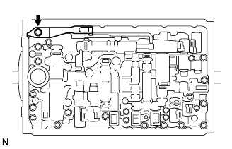
- Torque:
- 10 N*m{ 102 kgf*cm , 7 ft.*lbf }
| 49. INSTALL TRANSMISSION WIRE |
Coat a new O-ring with ATF.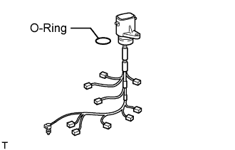
Install the O-ring to the transmission wire.
Install the transmission wire harness.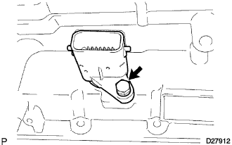
Install the bolt.
- Torque:
- 5.4 N*m{ 55 kgf*cm , 48 in.*lbf }
Connect the 9 solenoid connectors.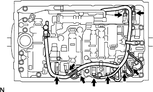
Install the ATF temperature sensor.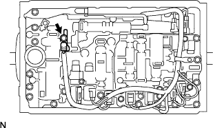
- Torque:
- 10 N*m{ 102 kgf*cm , 7 ft.*lbf }
Install the clamp and the 2 bolts.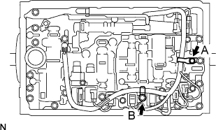
- Torque:
- Bolt A:
- 6.4 N*m{ 65 kgf*cm , 57 in.*lbf }
- Bolt B:
- 10 N*m{ 102 kgf*cm , 7 ft.*lbf }
| 50. INSTALL VALVE BODY OIL STRAINER ASSEMBLY |
Coat a new O-ring with ATF, and install it to the valve body oil strainer assembly.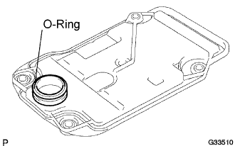
Install the oil strainer with the 4 bolts.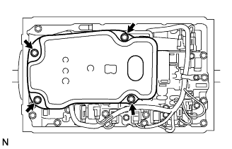
- Torque:
- 10 N*m{ 102 kgf*cm , 7 ft.*lbf }
| 51. INSTALL TRANSMISSION OIL CLEANER MAGNET |
Install the 3 transmission oil cleaner magnets.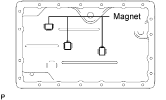
| 52. INSTALL AUTOMATIC TRANSMISSION OIL PAN SUB-ASSEMBLY |
Install a new gasket on the oil pan.
Install and tighten the 20 bolts.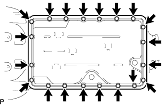
- Torque:
- 4.4 N*m{ 45 kgf*cm , 39 in.*lbf }
Install a new gasket and the drain plug.
- Torque:
- 20 N*m{ 204 kgf*cm , 15 ft.*lbf }
Install a new gasket and the overflow plug.
- Torque:
- 20 N*m{ 204 kgf*cm , 15 ft.*lbf }
| 53. INSTALL AUTOMATIC TRANSMISSION EXTENSION HOUSING OIL SEAL |
Coat the lip of a new oil seal with MP grease.
Using SST and a hammer, install a new oil seal until it fits with the extension housing.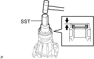
- SST
- 09325-40010
- Oil seal drive in depth:
- 5.4 to 5.8 mm (0.213 to 0.228 in.)
| 54. INSTALL EXTENSION HOUSING DUST DEFLECTOR |
Using SST and a press, install a new extension housing dust deflector.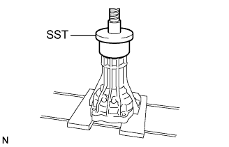
- SST
- 09950-60020
(09951-01030)
| 55. INSTALL EXTENSION (ATM) HOUSING SUB-ASSEMBLY |
Install the transmission case adapter radial ball bearing to the extension housing.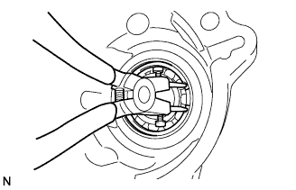
Using a snap ring pliers, install the snap ring.
Install the thrust needle roller bearing and the 2 bearing races.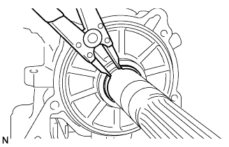
Using a snap ring expander, install the snap ring.
Using a feeler gauge, measure the clearance between the snap ring and the race.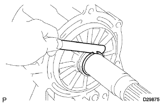
- Clearance:
- 0.02 to 0.12 mm (0.0008 to 0.0047 in.)
- HINT:
- There are 12 different thicknesses for the race.
- Flange thickness:
NO.
Thickness
NO.
Thickness
1
3.80 mm (0.1496 in.)
7
4.10 mm (0.1614 in.)
2
3.85 mm (0.1516 in.)
8
4.15 mm (0.1634 in.)
3
3.90 mm (0.1535 in.)
9
4.20 mm (0.1653 in.)
4
3.95 mm (0.1555 in.)
10
4.25 mm (0.1673 in.)
5
4.00 mm (0.1575 in.)
11
4.30 mm (0.1693 in.)
6
4.05 mm (0.1594 in.)
12
4.35 mm (0.1713 in.)
Clean the threads of the bolts and the case with white gasoline.
Apply FIPG to the extension housing as shown in the illustration.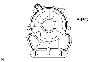
- FIPG:
- Seal Packing 1281, THREE BOND 1281 or equivalent
Install the extension housing with 6 new bolts.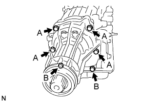
- Torque:
- 34 N*m{ 345 kgf*cm , 25 ft.*lbf }
- HINT:
- Each bolt length is indicated below.
- Bolt length:
- Bolt A:
- 45 mm (1.772 in.)
- Bolt B:
- 35 mm (1.378 in.)
| 56. INSTALL AUTOMATIC TRANSMISSION HOUSING |
Clean the threads of the bolts and the case with white gasoline.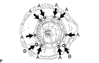
Install the transmission housing with the 10 bolts.
- Torque:
- A {14 mm (0.551 in.) bolt}:
- 34 N*m{ 347 kgf*cm , 25 ft.*lbf }
- B {17 mm (0.669 in.) bolt}:
- 57 N*m{ 581 kgf*cm , 42 ft.*lbf }
| 57. INSTALL AUTOMATIC TRANSMISSION BREATHER TUBE |
Install the breather tube.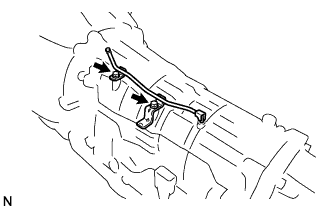
Install the 2 bolts.
- Torque:
- 5.4 N*m{ 55 kgf*cm , 48 in.*lbf }
| 58. INSTALL TRANSMISSION REVOLUTION SENSOR |
Coat 2 new O-rings with ATF, and install them to the transmission revolution sensors.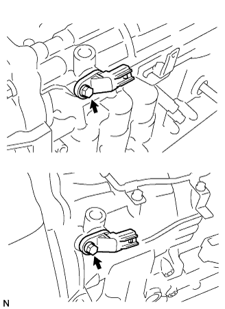
Install the 2 transmission revolution sensors.
Install the 2 bolts.
- Torque:
- 5.4 N*m{ 55 kgf*cm , 48 in.*lbf }
| 59. INSTALL TRANSMISSION OIL COOLER |
Coat 2 new O-rings with ATF, and install them to the transmission oil cooler.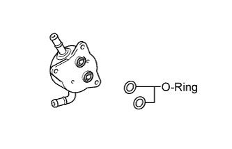
Install the transmission oil cooler with the 3 bolts.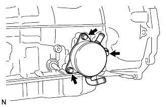
- Torque:
- 21 N*m{ 214 kgf*cm , 16 ft.*lbf }
| 60. INSTALL PARK/NEUTRAL POSITION SWITCH ASSEMBLY |
Install the park/neutral position switch onto the manual valve lever shaft, and temporarily install the adjusting bolt.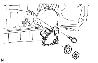
Install a new lock washer. Install and tighten the nut.
- Torque:
- 6.9 N*m{ 70 kgf*cm , 61 in.*lbf }
Using the control shaft lever, turn the manual lever shaft back all the way and then forward 2 notches. It is now in neutral.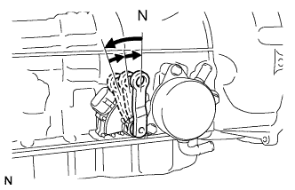
Align the neutral basic line with the switch groove as shown in the illustration, and tighten the adjusting bolt.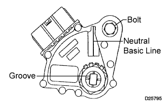
- Torque:
- 13 N*m{ 130 kgf*cm , 9 ft.*lbf }
Using a screwdriver, bend the tabs of the lock washer.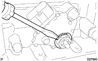
- HINT:
- Bend at least 2 of the lock washer tabs.
| 61. INSTALL TRANSMISSION CONTROL SHAFT LEVER RH |
Install the control shaft lever RH, washer and the nut.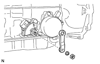
- Torque:
- 16 N*m{ 163 kgf*cm , 12 ft.*lbf }
| 62. INSTALL TRANSMISSION CASE COVER |
Install the transmission case cover with the 2 bolts.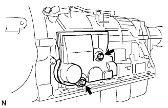
- Torque:
- 5.4 N*m{ 55 kgf*cm , 48 in.*lbf }