DISASSEMBLY
Removal / installation
| 1. FIX CLUTCH DRUM AND INPUT SHAFT |

Place the oil pump onto the torque converter clutch, and then place the reverse clutch drum sub-assembly and input shaft onto the oil pump.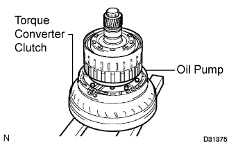

| 2. REMOVE REVERSE CLUTCH HUB SUB-ASSEMBLY |
Using a screwdriver, remove the snap ring from the reverse clutch drum sub-assembly and input shaft.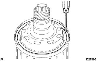
Remove the reverse clutch hub sub-assembly with the reverse clutch reaction sleeve, the clutch cushion plate, the reverse clutch flange, the 5 rear clutch discs, and the 4 clutch plates from the forward clutch hub.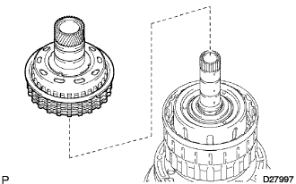
| 3. REMOVE REVERSE CLUTCH REACTION SLEEVE |
Remove the reverse clutch reaction sleeve from the reverse clutch hub sub-assembly.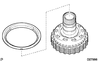
| 4. REMOVE NO. 3 CLUTCH DISC |
Remove the clutch cushion plate, the reverse clutch flange, the 3 plates and the 4 discs from the reverse clutch hub.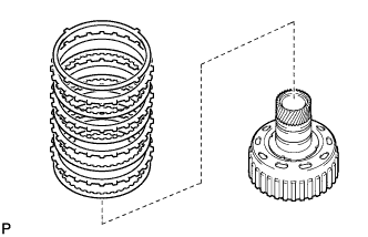
| 5. INSPECT NO. 3 CLUTCH DISC |
Check whether the sliding surfaces of the discs, the plates, and the flange are worn or burnt.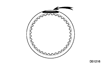
If necessary, replace them.- NOTICE:
- If the linings of the discs are peeled off or discolored, or even a part of the printed numbers is damaged, replace all discs.
- If the linings of the discs are peeled off or discolored, or even a part of the printed numbers is damaged, replace all discs.
- Before assembling new discs, soak them in ATF for at least 15 minutes.
- Before assembling new discs, soak them in ATF for at least 15 minutes.
| 6. INSPECT REVERSE CLUTCH HUB SUB-ASSEMBLY |
Inspect the pack clearance of the reverse clutch hub sub-assembly.
Using a dial indicator, measure the reverse clutch piston stroke (distance A) and the moving distance (distance B) of the reverse clutch flange at both ends across a diameter while blowing air (392 kPa, 4 kgf/cm2, 57 psi) from the oil hole as shown in the illustration, and calculate the average.
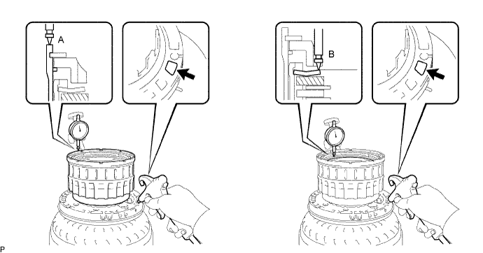
- HINT:
- Piston stroke A = 1.62 to 2.68 mm (0.0638 to 0.1055 in.)
- Flange moving distance B = 1.22 to 1.67 mm (0.0480 to 0.0657 in.)
- Pack clearance = Piston stroke A - Flange moving distance B - 0.02 mm (0.0008 in.)
- Pack Clearance:
- 0.4 to 0.7 mm (0.016 to 0.028 in.)
- NOTICE:
- Install a selective flange {t = 2.8 mm (0.110 in.)} when measuring the moving distance (shaded area in the illustration).
If the pack clearance is outside the specified range, select and install a clutch flange that brings the pack clearance within the specified range.
- HINT:
- There are 12 types of flanges that can be used to adjust the pack clearance. Select the one with the most appropriate thickness.
- Flange thickness:
No.
Thickness
0
2.4 mm (0.094 in.)
1
2.5 mm (0.098 in.)
2
2.6 mm (0.102 in.)
3
2.7 mm (0.106 in.)
4
2.8 mm (0.110 in.)
5
2.9 mm (0.114 in.)
6
3.0 mm (0.118 in.)
7
3.1 mm (0.122 in.)
8
3.2 mm (0.126 in.)
9
3.3 mm (0.130 in.)
A
3.4 mm (0.134 in.)
B
3.5 mm (0.138 in.)
| 7. REMOVE CLUTCH HUB SUB-ASSEMBLY |
Remove the clutch hub sub-assembly and thrust washer from the reverse clutch drum sub-assembly.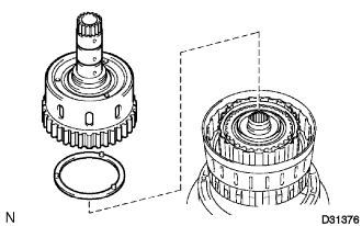
Remove the 2 thrust needle roller bearings and the thrust bearing race from the clutch hub sub-assembly.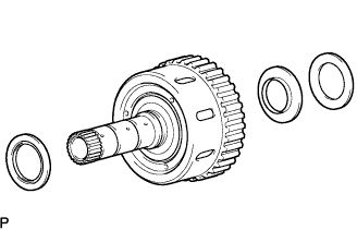
| 8. INSPECT CLUTCH HUB SUB-ASSEMBLY |
Using a dial indicator, measure the inside diameter of the clutch hub bushing.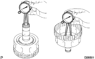
- Standard inside diameter:
- 23.037 to 23.062 mm (0.907 to 0.908 in.)
| 9. REMOVE COAST CLUTCH HUB SUB-ASSEMBLY |
Remove the coast clutch hub sub-assembly from the reverse clutch drum sub-assembly.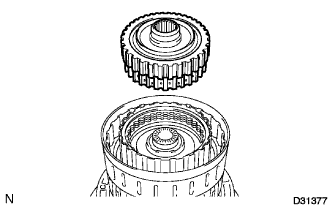
| 10. INSPECT NO. 4 ONE WAY CLUTCH ASSEMBLY |
Hold the coast clutch hub and turn the one way clutch assembly.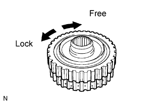
Check that the one way clutch assembly turns freely clockwise and locks counterclockwise.
If there is a problem with the one way clutch, replace it.
| 11. REMOVE NO. 4 ONE WAY CLUTCH ASSEMBLY |
Remove the No. 4 one way clutch assembly and the clutch hub thrust washer from the coast clutch hub.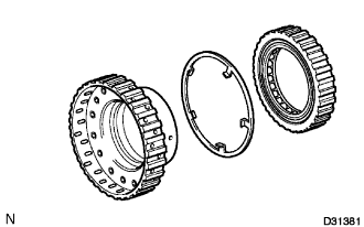
| 12. REMOVE NO. 1 CLUTCH DISC |
Using a screwdriver, remove the hole snap ring.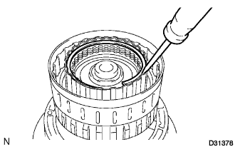
Remove the flange, cushion plate, 4 discs and 5 plates from the input shaft.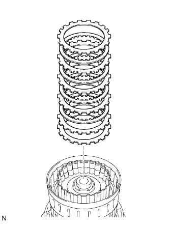
| 13. INSPECT NO. 1 CLUTCH DISC |
Check whether the sliding surfaces of the discs, the plates, and the flange are worn or burnt.
If necessary, replace them.- NOTICE:
- If the linings of the discs are peeled off or discolored, or even a part of the printed numbers is damaged, replace all discs.
- If the linings of the discs are peeled off or discolored, or even a part of the printed numbers is damaged, replace all discs.
- Before assembling new discs, soak them in ATF for at least 15 minutes.
- Before assembling new discs, soak them in ATF for at least 15 minutes.
| 14. REMOVE COAST CLUTCH DISC |
Using a screwdriver, remove the hole snap ring.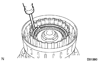
Remove the flange, the 4 discs and the 4 plates from the input shaft.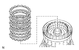
| 15. INSPECT COAST CLUTCH DISC |
Check whether the sliding surfaces of the discs, the plates, and the flange are worn or burnt.
If necessary, replace them.- NOTICE:
- If the linings of the discs are peeled off or discolored, or even a part of the printed numbers is damaged, replace all discs.
- If the linings of the discs are peeled off or discolored, or even a part of the printed numbers is damaged, replace all discs.
- Before assembling new discs, soak them in ATF for at least 15 minutes.
- Before assembling new discs, soak them in ATF for at least 15 minutes.
| 16. REMOVE INPUT SHAFT |
Remove the thrust needle roller bearing and the thrust bearing race from the input shaft.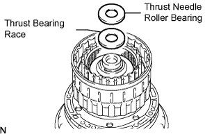
Remove the input shaft from the reverse clutch drum sub-assembly.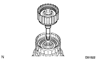
Remove the thrust needle roller bearing and thrust bearing race from the reverse clutch drum sub-assembly.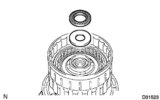
| 17. REMOVE INPUT SHAFT OIL SEAL RING |
Remove the 4 oil seal rings from the input shaft.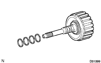
| 18. REMOVE NO. 1 CLUTCH BALANCER |
Place SST on the No. 1 clutch balancer, and compress the return spring with a press.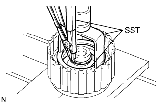
- SST
- 09350-30020
(09350-07040)
09316-20011
Using the SST, remove the snap ring.
- SST
- 09350-30020
(09350-07070)
Remove the No. 1 clutch balancer and the forward clutch return spring from the input shaft.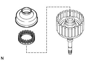
Remove the D-ring from the No. 1 clutch balancer.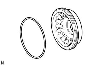
| 19. INSPECT FORWARD CLUTCH RETURN SPRING SUB-ASSEMBLY |
Using vernier calipers, measure the free length of the spring together with the spring seat.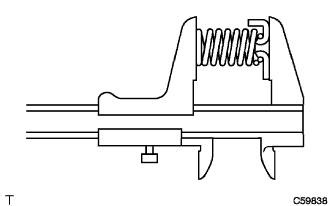
- Standard free length:
- 26.29 mm (1.035 in.)
| 20. REMOVE FORWARD CLUTCH PISTON SUB-ASSEMBLY |
Holding the forward clutch piston by hand, apply compressed air (392 kPa, 4.0 kgf/cm2, 57 psi) to the input shaft to remove the forward clutch piston.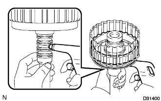
Remove the coast clutch piston from the forward clutch piston.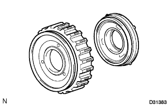
Remove the O-ring from the input shaft.
| 21. REMOVE REVERSE CLUTCH FLANGE |
Remove the reverse clutch flange from the reverse clutch drum sub-assembly.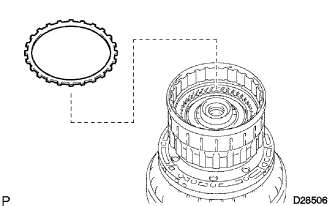
| 22. REMOVE NO. 2 DIRECT CLUTCH DISC |
Using a screwdriver, remove the 2 hole snap rings from the reverse clutch drum sub-assembly.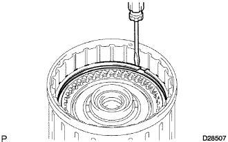
Remove the direct clutch flange, the 5 plates and the 5 discs from the reverse clutch drum sub-assembly.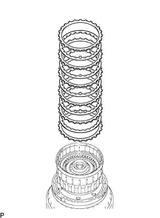
| 23. INSPECT NO. 2 DIRECT CLUTCH DISC |
Check whether the sliding surfaces of the discs, the plates, and the flange are worn or burnt.
If necessary, replace them.- NOTICE:
- If the linings of the discs are peeled off or discolored, or even a part of the printed numbers is damaged, replace all discs.
- If the linings of the discs are peeled off or discolored, or even a part of the printed numbers is damaged, replace all discs.
- Before assembling new discs, soak them in ATF for at least 15 minutes.
- Before assembling new discs, soak them in ATF for at least 15 minutes.
| 24. REMOVE NO. 3 CLUTCH BALANCER |
Place SST on the No. 3 clutch balancer, and compress the return spring with a press.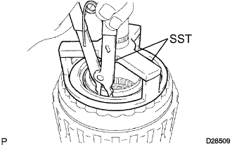
- SST
- 09387-00070
Using SST, remove the snap ring.
- SST
- 09350-30020
(09350-07070)
Remove the No. 3 clutch balancer.
| 25. REMOVE REVERSE CLUTCH RETURN SPRING SUB-ASSEMBLY |
Remove the reverse clutch return spring and the O-ring from the reverse clutch piston.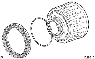
| 26. INSPECT REVERSE CLUTCH RETURN SPRING SUB-ASSEMBLY |
Using vernier calipers, measure the free length of the spring together with the spring seat.
- Standard free length:
- 21.03 mm (0.828 in.)
| 27. REMOVE REVERSE CLUTCH PISTON SUB-ASSEMBLY |
Remove the reverse clutch piston sub-assembly from the reverse clutch drum sub-assembly.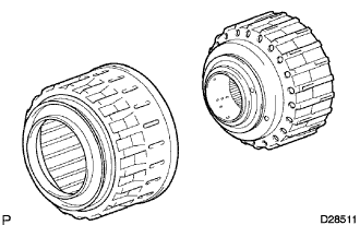
Remove the O-ring from the reverse clutch piston sub-assembly.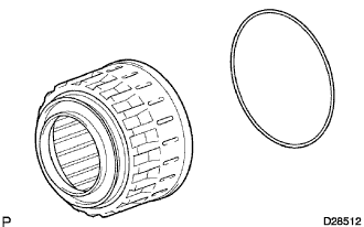
Remove the O-ring from the reverse clutch drum sub-assembly.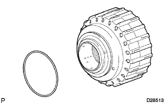
| 28. REMOVE DIRECT CLUTCH PISTON SUB-ASSEMBLY |
Place SST on the direct clutch piston, and compress the return spring with a press.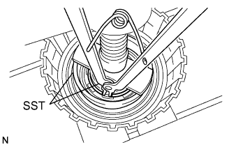
- SST
- 09350-30020
(09350-07070)
09518-36020
Using SST, remove the snap ring.
Remove the No. 2 clutch balancer and the direct clutch return spring sub-assembly.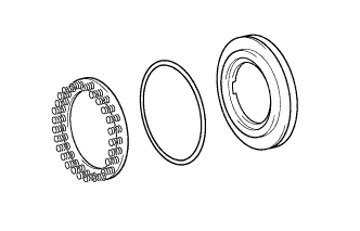
Remove the O-ring from the No. 2 clutch balancer.
Using 2 screwdrivers, remove the direct clutch piston sub-assembly from the reverse clutch drum sub-assembly.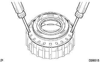
Remove the 2 O-rings from the direct clutch piston sub-assembly.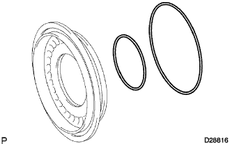
| 29. INSPECT DIRECT CLUTCH RETURN SPRING SUB-ASSEMBLY |
Using vernier calipers, measure the free length of the spring together with the spring seat.
- Standard free length:
- 20.02 mm (0.788 in.)