REASSEMBLY
Removal / installation
| 1. INSTALL DIRECT CLUTCH PISTON SUB-ASSEMBLY |

Coat 2 new O-rings with ATF, and install them in the direct clutch piston.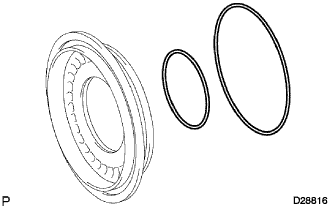

Coat a new O-ring with ATF, and install it to the No. 2 clutch balancer.
Install the No. 2 clutch balancer and the direct clutch return spring to the direct clutch piston sub-assembly.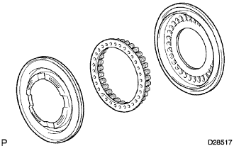
Press the direct clutch piston into the reverse clutch drum sub-assembly by hands.
- NOTICE:
- Do not damage the O-rings.
Place SST on the direct clutch piston, and compress the return spring with a press.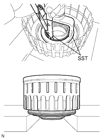
- SST
- 09320-89010
09350-30020 (09350-07070)
Install the snap ring with a snap ring expander.
- NOTICE:
- Be sure that the end gap of the snap ring is not aligned with the spring retainer claw.
- Stop pressing when the spring sheet is lowered to the place 1 to 2 mm (0.039 to 0.078 in.) from the snap ring groove to prevent the spring sheet from being deformed.
- Do not expand the snap ring excessively.
- Be sure that the end gap of the snap ring is not aligned with the spring retainer claw.
Set the end gap of the snap ring in the piston as shown in the illustration.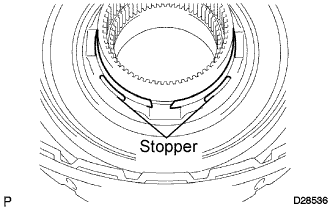
| 2. INSTALL REVERSE CLUTCH PISTON SUB-ASSEMBLY |
Coat a new O-ring with ATF, and install it on the reverse clutch drum sub-assembly.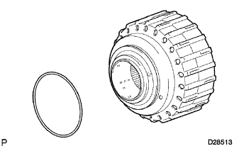
Coat a new O-ring with ATF, and install it on the reverse clutch piston sub-assembly.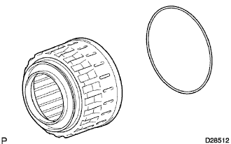
Press the clutch drum sub-assembly into the reverse clutch piston with both hands.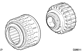
- NOTICE:
- Do not damage the O-ring.
| 3. INSTALL REVERSE CLUTCH RETURN SPRING SUB-ASSEMBLY |
Coat a new O-ring with ATF, and install it on the reverse clutch piston sub-assembly.
Install the reverse clutch return spring onto the reverse clutch piston sub-assembly.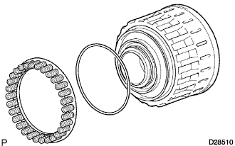
| 4. INSTALL NO. 3 CLUTCH BALANCER |
Install the No. 3 clutch balancer to the reverse clutch return spring.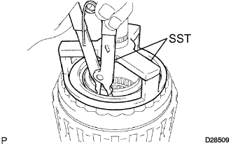
Place SST on the No. 3 clutch balancer, and compress the clutch balancer with a press.
- SST
- 09387-00070
Install the snap ring with a snap ring expander.
- SST
- 09350-30020
(09350-07070)
- NOTICE:
- Be sure that the end gap of the snap ring is not aligned with the spring retainer claw.
- Be sure that the end gap of the snap ring is not aligned with the spring retainer claw.
- Stop pressing when the spring sheet is lowered to the place 1 to 2 mm (0.039 to 0.078 in.) from the snap ring groove to prevent the spring sheet from being deformed.
- Stop pressing when the spring sheet is lowered to the place 1 to 2 mm (0.039 to 0.078 in.) from the snap ring groove to prevent the spring sheet from being deformed.
- Do not expand the snap ring excessively.
- Do not expand the snap ring excessively.
Set the end gap of the snap ring in the piston as shown in the illustration.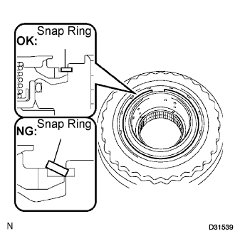
| 5. INSTALL NO. 2 DIRECT CLUTCH DISC |
Install the reverse clutch flange, the 5 plates and the 5 discs on the reverse clutch drum sub-assembly.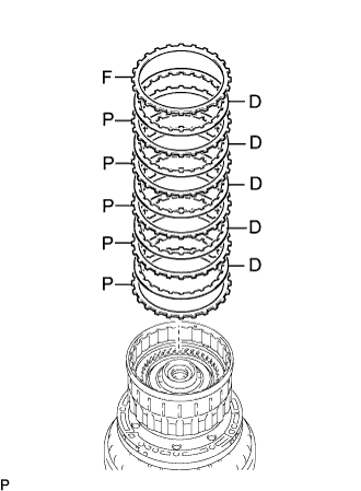
- Install in order:
- P = Plate, D = Disc, F = Flange,
F - D - P - D - P - D - P - D - P - D - P
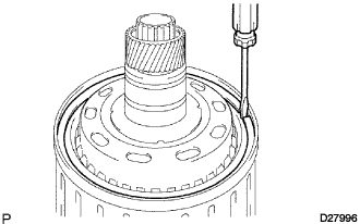
Using a screwdriver, install the 2 hole snap rings on the reverse clutch drum sub-assembly.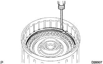
| 6. INSPECT PACK CLEARANCE OF DIRECT CLUTCH |
Inspect the pack clearance of the No. 2 direct clutch.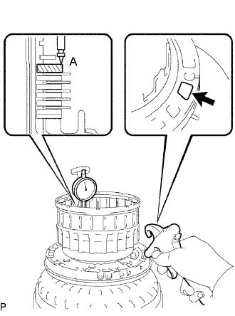
Using a dial indicator, measure the moving distance (distance A) of the clutch flange at both ends across a diameter while blowing air to the oil hole as shown in the illustration, and calculate the average.
- HINT:
- Flange moving distance A = 0.24 to 1.12 mm (0.0094 to 0.0441 in.)
- Pack clearance = Flange moving distance A - 0.03 mm (0.0012 in.)
- Pack Clearance:
- 0.5 to 0.8 mm (0.020 to 0.031 in.)
- NOTICE:
- Install a selective flange {t = 3.4 mm (0.134 in.)} when measuring the moving distance (shaded area in the illustration).
If the pack clearance is outside the specified range, select and install a clutch flange that brings the pack clearance within the specified range.
- HINT:
- There are 9 types of flanges that can be used to adjust the pack clearance. Select the one with the most appropriate thickness.
- Flange thickness:
No.
Thickness
0
3.0 mm (0.118 in.)
1
3.1 mm (0.122 in.)
2
3.2 mm (0.126 in.)
3
3.3 mm (0.130 in.)
4
3.4 mm (0.134 in.)
5
3.5 mm (0.138 in.)
6
3.6 mm (0.142 in.)
7
3.7 mm (0.146 in.)
8
3.8 mm (0.150 in.)
| 7. INSTALL REVERSE CLUTCH FLANGE |
Install the reverse clutch flange to the reverse clutch drum sub-assembly.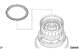
| 8. INSTALL REVERSE CLUTCH REACTION SLEEVE |
Install the reverse clutch reaction sleeve, the clutch cushion plate, the reverse clutch flange, the 4 reverse clutch discs, and the 3 clutch plates to the reverse clutch hub.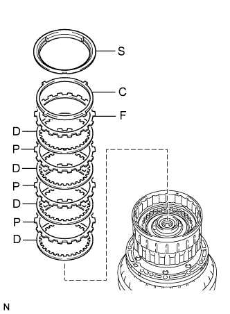
- Install in order:
- P = Plate, D = Disc, F = Flange, S = Sleeve, C = Cushion Plate
S - C - F - D - P - D - P - D - P - D
Using a screwdriver, install the hole snap ring.
| 9. INSPECT PACK CLEARANCE OF REVERSE CLUTCH |
Inspect the pack clearance of the reverse clutch hub sub-assembly.
Using a dial indicator, measure the reverse clutch piston stroke (distance A) and the moving distance (distance B) of the reverse clutch flange at both ends across a diameter while blowing air (392 kPa, 4 kgf/cm2, 57 psi) from the oil hole as shown in the illustration, and calculate the average.
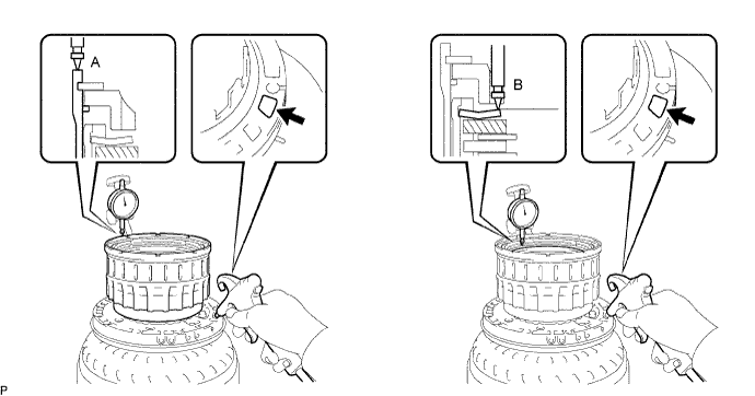
- HINT:
- Piston stroke A = 1.62 to 2.68 mm (0.0638 to 0.1055 in.)
- Flange moving distance B = 1.22 to 1.67 mm (0.0480 to 0.0657 in.)
- Pack clearance = Piston stroke A - Flange moving distance B - 0.02 mm (0.0008 in.)
- Pack Clearance:
- 0.4 to 0.7 mm (0.016 to 0.028 in.)
- NOTICE:
- Install a selective flange {t = 2.8 mm (0.110 in.)} when measuring the moving distance (shaded area in the illustration).
If the pack clearance is outside the specified range, select and install a clutch flange that brings the pack clearance within the specified range.
- HINT:
- There are 12 types of flanges that can be used to adjust the pack clearance. Select the one with the most appropriate thickness.
- Flange thickness:
No.
Thickness
0
2.4 mm (0.094 in.)
1
2.5 mm (0.098 in.)
2
2.6 mm (0.102 in.)
3
2.7 mm (0.106 in.)
4
2.8 mm (0.110 in.)
5
2.9 mm (0.114 in.)
6
3.0 mm (0.118 in.)
7
3.1 mm (0.122 in.)
8
3.2 mm (0.126 in.)
9
3.3 mm (0.130 in.)
A
3.4 mm (0.134 in.)
B
3.5 mm (0.138 in.)
| 10. REMOVE REVERSE CLUTCH REACTION SLEEVE |
Using a screwdriver, remove the snap ring from the reverse clutch drum sub-assembly.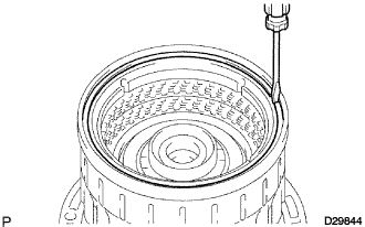
Remove the reverse clutch reaction sleeve, the clutch cushion plate, the reverse clutch flange, the 4 reverse clutch discs, and the 3 clutch plates from the reverse clutch hub sub-assembly.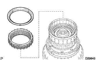
| 11. INSTALL FORWARD CLUTCH PISTON SUB-ASSEMBLY |
Install the coast clutch piston to the input shaft.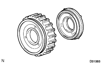
Install a new O-ring to the forward clutch.
Install the forward clutch piston sub-assembly to the input shaft.
| 12. INSTALL NO. 1 CLUTCH BALANCER |
Coat a new D-ring with ATF and install it on the No. 1 clutch balancer.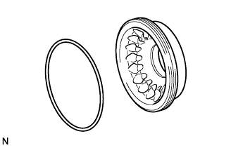
Install the No. 1 clutch balancer and the forward clutch return spring sub-assembly.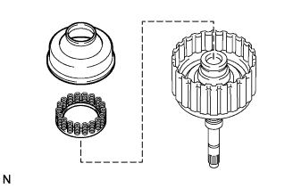
- NOTICE:
- Do not damage the D-ring.
Place SST on the No. 1 clutch balancer, and compress the return spring with a press.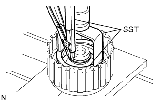
- SST
- 09350-30020
(09350-07040)
09316-20011
Using SST, Install the snap ring.
- SST
- 09350-30020
(09350-07070)
- NOTICE:
- Be sure that the end gap of the snap ring is not aligned with the spring retainer claw.
- Be sure that the end gap of the snap ring is not aligned with the spring retainer claw.
- Stop pressing when the spring sheet is lowered to the place 1 to 2 mm (0.039 to 0.078 in.) from the snap ring groove to prevent the spring sheet from being deformed.
- Stop pressing when the spring sheet is lowered to the place 1 to 2 mm (0.039 to 0.078 in.) from the snap ring groove to prevent the spring sheet from being deformed.
- Do not expand the snap ring excessively.
- Do not expand the snap ring excessively.
Set the end gap of the snap ring in the piston as shown in the illustration.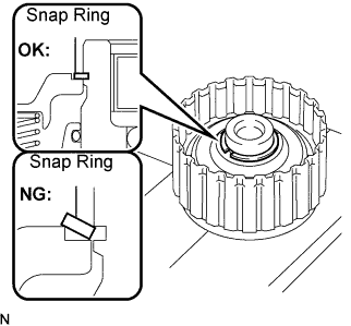
| 13. INSTALL COAST CLUTCH DISC |
Install the flange, the 4 discs and the 4 plates to the forward clutch piston.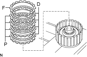
Using a screwdriver, install the hole snap ring.
| 14. INSPECT PACK CLEARANCE OF COAST CLUTCH |
Inspect the pack clearance of the No. 1 clutch.
Using a dial indicator, measure the moving distance (distance A) of the clutch flange at both ends across a diameter while blowing air from the oil hole as shown in the illustration, and calculate the average.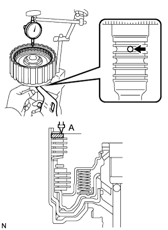
- HINT:
- Flange moving distance A = 0.14 to 0.17 mm (0.0055 to 0.0067 in.)
- Pack clearance = Flange moving distance A - 0.01 mm (0.00039 in.)
- Pack Clearance:
- 0.56 to 0.86 mm (0.0220 to 0.0339 in.)
- NOTICE:
- Install a selective flange {t = 3.5 mm (0.138 in.)} when measuring the moving distance (shaded area in the illustration).
If the pack clearance is outside the specified range, select and install a clutch flange that brings the pack clearance within the specified range.
- HINT:
- There are 10 types of flanges that can be used to adjust the pack clearance. Select the one with the most appropriate thickness.
- Flange thickness:
No.
Thickness
0
3.0 mm (0.118 in.)
1
3.1 mm (0.122 in.)
2
3.2 mm (0.126 in.)
3
3.3 mm (0.130 in.)
4
3.4 mm (0.134 in.)
5
3.5 mm (0.138 in.)
6
3.6 mm (0.142 in.)
7
3.7 mm (0.146 in.)
8
3.8 mm (0.150 in.)
9
3.9 mm (0.154 in.)
| 15. INSTALL NO. 1 CLUTCH DISC |
Install the flange, the 4 discs, 4 plates and clutch cushion plate to the input shaft assembly.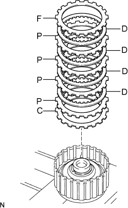
- Install in order:
- P = Plate, D = Disc, F = Flange, C = Cushion Plate
F - D - P - D - P - D - P - D - P - C
Using a screwdriver, install the hole snap ring.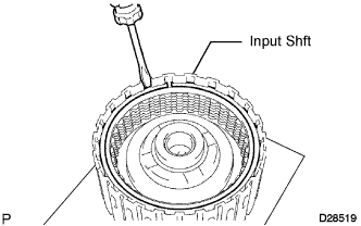
Install the thrust needle roller bearing and the thrust bearing race.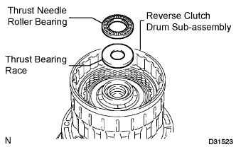
Inside
Outside
Thrust needle roller bearing
33.5 mm (1.319 in.)
48.0 mm (1.890 in.)
Thrust bearing race
37.0 mm (1.457 in.)
51.2 mm (2.016 in.)
| 16. INSTALL INPUT SHAFT OIL SEAL RING |
Coat 4 new oil seal rings with ATF.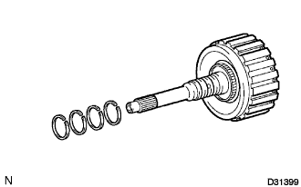
Squeeze the ends of the 4 oil seal rings together, and then install them to the input shaft groove.
- NOTICE:
- Do not expand the ring ends excessively.
- HINT:
- After installing the oil seal rings, check that they rotate smoothly.
| 17. INSPECT PACK CLEARANCE OF FORWARD CLUTCH |
Inspect the pack clearance of the coast clutch.
Using a dial indicator, measure the moving distance (distance A) of the clutch flange at both ends across a diameter while blowing air from the oil hole as shown in the illustration, and calculate the average.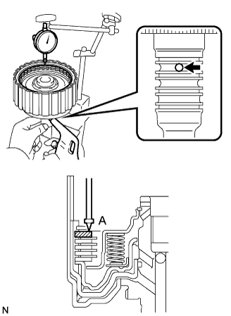
- HINT:
- Flange moving distance A = 0.02 to 1.01 mm (0.0008 to 0.0398 in.)
- Pack clearance = Flange moving distance A - 0.01 mm (0.00039 in.)
- Pack Clearance:
- 0.4 to 0.7 mm (0.0157 to 0.0276 in.)
- NOTICE:
- Install a selective flange {t = 3.5 mm (0.138 in.)} when measuring the moving distance (shaded area in the illustration).
If the pack clearance is outside the specified range, select and install a clutch flange that brings the pack clearance within the specified range.
- HINT:
- There are 10 types of flanges that can be used to adjust the pack clearance. Select the one with the most appropriate thickness.
- Flange thickness:
No.
Thickness
0
3.0 mm (0.118 in.)
1
3.1 mm (0.122 in.)
2
3.2 mm (0.126 in.)
3
3.3 mm (0.130 in.)
4
3.4 mm (0.134 in.)
5
3.5 mm (0.138 in.)
6
3.6 mm (0.142 in.)
7
3.7 mm (0.146 in.)
8
3.8 mm (0.150 in.)
9
3.9 mm (0.154 in.)
| 18. INSTALL INPUT SHAFT |
Install the input shaft to the reverse clutch drum sub-assembly.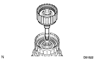
Install the thrust needle roller bearing and the thrust bearing race to the reverse clutch drum sub-assembly.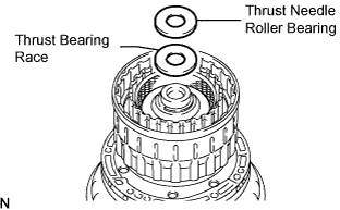
- Thrust needle roller bearing diameter:
Inside
Outside
Thrust needle roller bearing
20.0 mm (0.787 in.)
41.0 mm (1.614 in.)
Thrust bearing race
20.0 mm (0.787 in.)
35.6 mm (1.402 in.)
| 19. INSTALL COAST CLUTCH HUB SUB-ASSEMBLY |
Install the clutch hub thrust washer and the No. 4 one way clutch assembly to the coast clutch hub.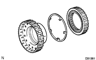
Install the coast clutch hub sub-assembly to the reverse clutch drum sub-assembly.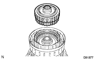
| 20. INSTALL CLUTCH HUB SUB-ASSEMBLY |
Install the 2 thrust needle roller bearings and No. 2 thrust bearing race to the clutch hub sub-assembly.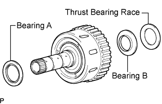
- Bearing and race diameter:
Inside
Outside
Bearing A
42.5 mm (1.673 in.)
61.2 mm (2.409 in.)
Bearing B
33.3 mm (1.311 in.)
51.2 mm (2.016 in.)
Thrust bearing race No. 2
31.0 mm (1.221 in.)
48.0 mm (1.890 in.)
Install the clutch hub thrust washer and forward clutch hub sub-assembly to the reverse clutch drum sub-assembly.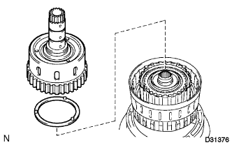
| 21. INSTALL NO. 3 CLUTCH DISC |
Install the clutch cushion plate, the reverse clutch flange, the 3 plates and the 4 discs to the reverse clutch hub.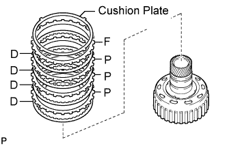
| 22. INSTALL REVERSE CLUTCH REACTION SLEEVE |
Install the reverse clutch reaction sleeve to the reverse clutch hub.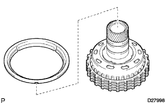
| 23. INSTALL REVERSE CLUTCH HUB SUB-ASSEMBLY |
Install the reverse clutch hub sub-assembly, the reverse clutch reaction sleeve, the clutch cushion plate, the reverse clutch flange, the 4 reverse clutch discs, and the 3 clutch plates to the reverse clutch drum sub-assembly.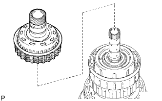
Using a screwdriver, install the snap ring on the reverse clutch drum sub-assembly and the input shaft assembly.