DIAGNOSIS SYSTEM
Troubleshooting
| EURO-OBD (EUROPE) |
Euro-OBD regulations require that the vehicle's on-board computer illuminates the Malfunction Indicator Lamp (MIL) on the instrument panel when the computer detects a malfunction in:
  |
The emission control system/components
The power train control components (which affect vehicle emissions)
The computer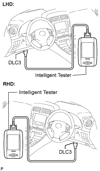
In addition, the applicable Diagnostic Trouble Codes (DTCs) prescribed by ISO 15765-4 are recorded in the ECM memory. If the malfunction does not reoccur in 3 consecutive trips, the MIL turns off automatically but the DTCs remain recorded in the ECM memory.
To check DTCs, connect the intelligent tester to the Data Link Connector3 (DLC3) of the vehicle.
The scan tool displays DTCs, the freeze frame data and a variety of the engine data.
The DTCs and freeze frame data can be erased with the scan tool (Click here).
| M-OBD (EXCEPT EUROPEAN SPEC.) |
OBD regulations require that the vehicle's on-board computer illuminates the MIL on the instrument panel when the computer detects a malfunction in:
|
|
The emission control system/components
The power train control components (which affect vehicle emissions)
The computer
In addition, the applicable DTCs are recorded in the ECM memory. If the malfunction does not recur in 3 consecutive trips, the MIL turns off automatically but the DTCs remain recorded in the ECM memory.
| NORMAL MODE AND CHECK MODE |
| 2-TRIP DETECTION LOGIC |
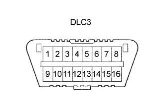
| DLC3 (Data Link Connector 3) |
- HINT:
- Connect the cable of the intelligent tester to the DLC3, turn the engine switch on (IG) and attempt to use the tester. If the display indicates that a communication error has occurred, there is a problem either with the vehicle or with the tester.
- If communication is normal when the tester is connected to another vehicle, inspect the DLC3 of the original vehicle.
- If communication is still not possible when the tester is connected to another vehicle, the problem may be in the tester itself. Consult the Service Department listed in the tester's instruction manual.
| Symbol |
Terminal No. |
Name |
Reference terminal |
Result |
Condition |
| SIL |
7 |
Bus "+" line |
5 - Signal ground |
Pulse generation |
During transmission |
| CG |
4 |
Chassis ground |
Body ground |
1Ω or less |
Always |
| SG |
5 |
Signal ground |
Body ground |
1Ω or less |
Always |
| BAT |
16 |
Battery positive |
Body ground |
9 to 14 V |
Always |
| CANH |
6 |
High-lever CAN bus line |
CANL |
54 to 69 Ω |
IG switch OFF |
| CANH |
6 |
High-lever CAN bus line |
Body ground |
1 MΩ or higher |
IG switch OFF |
| CANH |
6 |
High-lever CAN bus line |
CG |
1 kΩ or higher |
IG switch OFF |
| CANL |
14 |
Low-lever CAN bus line |
Body ground |
1 MΩ or higher |
IG switch OFF |
| CANL |
14 |
Low-lever CAN bus line |
CG |
1 kΩ or higher |
IG switch OFF |
| INSPECT BATTERY VOLTAGE |
- Standard Voltage:
- 11 to 14 V
| CHECK MIL |
Check that the MIL illuminates when turning the engine switch on (IG).
If the MIL does not illuminate, there is a problem in the MIL circuit (Click here).When the engine is started, the MIL should turn off.
| ALL READINESS |