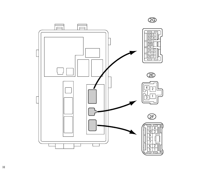
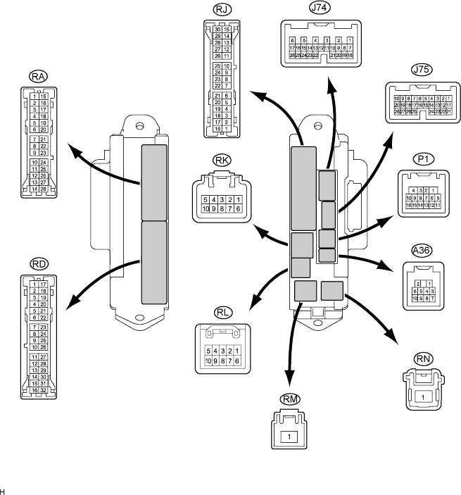
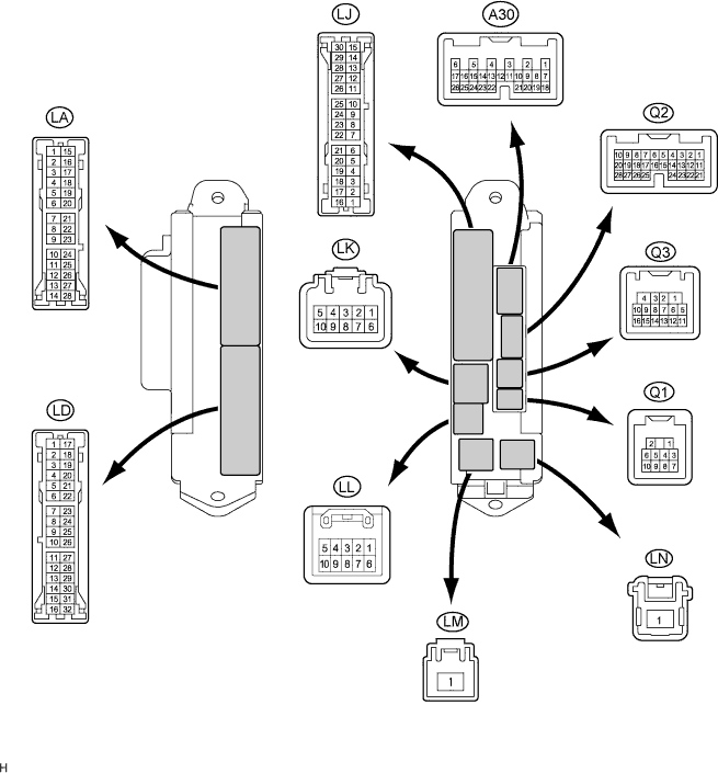
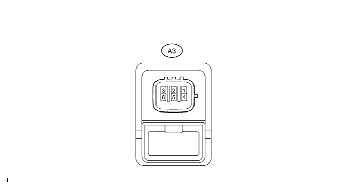
Symbols (Terminal No.)
|
Wiring Color
|
Terminal Description
|
Condition
|
Specified Condition
|
FMIG (2E-3) - E (2F-1)
|
B-Y - W-B
|
IG signal circuit (to IG relay)
|
Engine switch off
|
Below 1 V
|
Engine switch on (IG)
|
10 to 14 V
|
FMB3 (2E-4) - E (2F-1)
|
G-R - W-B
|
Power source circuit (from battery)
|
Always
|
10 to 14 V
|
E (2F-1) - Body ground
|
W-B - Body ground
|
Ground circuit
|
Always
|
Below 1 V
|
W+ (2F-4) - E (2F-1)
|
L - W-B
|
Windshield washer motor circuit
|
Windshield washer motor OFF
|
Below 1 V
|
Windshield washer motor ON
|
10 to 14 V
|
MPX1 (2F-5) - E (2F-1)
|
L - W-B
|
Multiplex communication signal circuit
|
Engine switch on (IG)
|
Signal waveform
|
MPX2 (2F-6) - E (2F-1)
|
GR - W-B
|
Multiplex communication signal circuit
|
Engine switch on (IG)
|
Signal waveform
|
FRWA (2F-8) - E (2F-1)
|
L-O - W-B
|
Headlight cleaner operation signal
|
Windshield washer motor OFF
|
4.5 to 5.5 V
|
Windshield washer motor ON
|
Below 1 V
|
WLVL (2F-7) - E (2F-1)
|
V - W-B
|
Washer fluid level sensor signal
|
Washer fluid level is normal
|
10 to 14 V
|
Washer fluid is empty
|
Below 1 V
|
Symbols (Terminal No.)
|
Wiring Color
|
Terminal Description
|
Condition
|
Specified Condition
|
MPX1 (RA-20) - GND2 (RD-7)
|
GR - W-B (*3)
|
Multiplex communication signal circuit
|
Engine switch on (IG)
|
Signal waveform
|
GND2 (RD-7) - Body ground
|
W-B - Body ground
|
Ground circuit
|
Always
|
Below 1 V
|
MPX1 (RJ-21) - GND2 (RD-7)
|
GR - W-B
|
Multiplex communication signal circuit
|
Engine switch on (IG)
|
Signal waveform
|
BECU (RK-5) - GND2 (RD-7)
|
G-R - W-B
|
ECU power supply (from battery)
|
Always
|
10 to 14 V
|
PKB (RL-9) - GND2 (RD-7) (*1)
PKB (RA-12) - GND2 (RD-7) (*2)
|
Y-B - W-B(*1)
Y - W-B(*2)
|
Parking brake switch circuit
|
Parking brake pedal is depressed
|
Below 1 V
|
Parking brake pedal is released
|
10 to 14 V
|
HDLO (A36-4) - GND2 (RD-7)
|
R - W-B
|
Headlight signal (to headlight cleaner relay)
|
Headlight switch is OFF
|
10 to 14 V
|
Headlight switch is LOW
|
Below 1 V
|
MPX2 (J75-21) - GND2 (RD-7)
|
GR - W-B
|
Multiplex communication signal circuit
|
Engine switch on (IG)
|
Signal waveform
|
Symbols (Terminal No.)
|
Wiring Color
|
Terminal Description
|
Condition
|
Specified Condition
|
GND (LD-3) - Body ground
|
W-B - Body ground
|
Ground circuit
|
Always
|
Below 1 V
|
SGND (LD-8) - Body ground
|
W-B - Body ground
|
Signal ground circuit
|
Always
|
Below 1 V
|
SGND (LD-9) - Body ground
|
W-B - Body ground
|
Signal ground circuit
|
Always
|
Below 1 V
|
WIG (LK-9) - GND (LD-3)
|
L - W-B
|
Front wiper motor power source circuit
|
Engine switch off
|
Below 1 V
|
Engine switch on (IG)
|
10 to 14 V
|
MPXB (LD-18) - GND (LD-3)
|
LG - W-B
|
ECU power supply (from battery)
|
Always
|
10 to 14 V
|
IG (LM-1) - GND (LD-3)
|
W - W-B
|
Power source circuit (from battery)
|
Always
|
10 to 14 V
|
S/S (A30-1) - GND (LD-3)
|
Y - W-B
|
Front wiper motor power supply circuit (LOW signal)
|
Front wiper switch OFF
|
Below 1 V
|
Front wiper switch LOW
|
10 to 14 V
|
+2 (A30-2) - GND (LD-3)
|
R-L - W-B
|
Front wiper motor power supply circuit (HI signal)
|
Front wiper switch OFF
|
Below 1 V
|
Front wiper switch HI
|
10 to 14 V
|
S/M (A30-3) - GND (LD-3)
|
G - W-B
|
Front wiper motor operation signal
|
Front wiper is operated
|
10 to 14 V
|
Front wiper is stopped
|
Below 1 V
|
MPX2 (A30-17) - GND (LD-3)
|
GR - W-B
|
Multiplex communication signal circuit
|
Engine switch on (IG)
|
Signal waveform
|
2S (Q2-11) - GND (LD-3)
|
B - W-B
|
Front wiper switch HI signal (to combination switch)
|
Front wiper switch OFF
|
10 to 14 V
|
Front wiper switch HI
|
Below 1 V
|
MPX1 (Q3-15) - GND (LD-3)
|
GR - W-B
|
Multiplex communication signal circuit
|
Engine switch on (IG)
|
Signal waveform
|
Symbols (Terminal No.)
|
Wiring Color
|
Terminal Description
|
Condition
|
Specified Condition
|
IG (A3-3) - E (A3-4)
|
Y - W-B
|
Engine switch on (IG) signal (Power source circuit)
|
Engine switch off
|
Below 1 V
|
IG (A3-3) - E (A3-4)
|
Y - W-B
|
Engine switch on (IG) signal (Power source circuit)
|
Engine switch on (IG)
|
10 to 14 V
|
PB (A3-6) - E (A3-4)
|
W-G - W-B
|
Headlight cleaner motor operation signal
|
Headlight cleaner motor is stopped
|
Below 1 V
|
PB (A3-6) - E (A3-4)
|
W-G - W-B
|
Headlight cleaner motor operation signal
|
Headlight cleaner motor is operating
|
10 to 14 V
|
HDLO (A3-1) - E (A3-4)
|
R - W-B
|
Daytime running light system operation signal
|
Daytime running light is not operating
|
Below 1 V
|
HDLO (A3-1) - E (A3-4)
|
R - W-B
|
Daytime running light system operation signal
|
Daytime running light is operating
|
10 to 14 V
|
H (A3-2) - E (A3-4)
|
R-G - W-B
|
Headlight cleaner switch operation signal
|
Headlight cleaner switch is OFF
|
Below 1 V
|
H (A3-2) - E (A3-4)
|
R-G - W-B
|
Headlight cleaner switch operation signal
|
Headlight cleaner switch is ON
|
10 to 14 V
|
E (A3-4) - Body ground
|
W-B - Body ground
|
Body ground
|
Always
|
Below 1 V
|
FRWA (A3-5) - E (A3-4)
|
L-O - W-B
|
Front washer motor operation signal
|
Front washer switch is OFF
|
Below 1 V
|
FRWA (A3-5) - E (A3 -4)
|
L-O - W-B
|
Front washer motor operation signal
|
Front washer switch is ON
|
10 to 14 V
|