Wiper Switch (HI Speed) Circuit
Circuit diagnosis
DESCRIPTION
The main body ECU LH (cowl side J/B LH) receives a HI position signal from the windshield wiper switch assembly to operate the wiper motor at HI speed.Even if the ECU malfunctions, this circuit structure enables it to operate the wiper in HI operation mode.
WIRING DIAGRAM
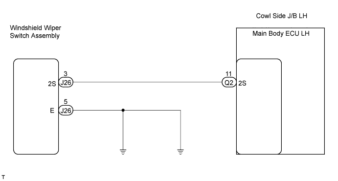

INSPECTION PROCEDURE
| 1. CHECK MAIN BODY ECU LH (COWL SIDE J/B LH) |

Measure the voltage according to the value(s) in the table below.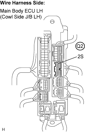
- Standard voltage:
Tester Connection
Condition
Specified Condition
Q2-11 (2S) - Body ground
Wiper switch not in HI position
10 to 14 V
Q2-11 (2S) - Body ground
Wiper switch in HI position
Below 1 V
|
|
||||

| OK | ||
 |
||
| ||
| 2. INSPECT WINDSHIELD WIPER SWITCH ASSEMBLY (COMBINATION SWITCH ECU) |
Measure the resistance according to the value(s) in the table below.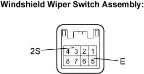
- Standard resistance:
Tester Connection
Condition
Specified Condition
3 (2S) - 5 (E)
Wiper switch in HI position
Below 1 Ω
3 (2S) - 5 (E)
Wiper switch not in HI position
10 kΩ or higher
|
|
||||

| OK | |
 |
| 3. CHECK HARNESS AND CONNECTOR (WINDSHIELD WIPER SWITCH - BODY GROUND) |
Disconnect the J26 windshield wiper switch assembly connector.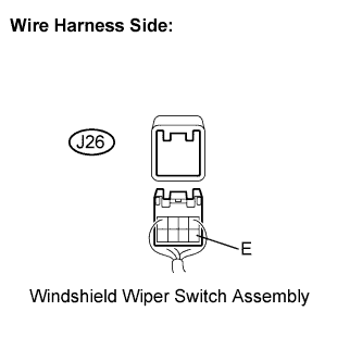
Measure the resistance according to the value(s) in the table below.
- Standard resistance:
Tester Connection
Condition
Specified Condition
J26-5 (E) - Body ground
Always
Below 1 Ω
|
|
||||
| OK | |
|
| 4. CHECK HARNESS AND CONNECTOR (WINDSHIELD WIPER SWITCH - MAIN BODY ECU LH (COWL SIDE J/B)) |
Disconnect the Q2 main body ECU LH (cowl side J/B LH) connector.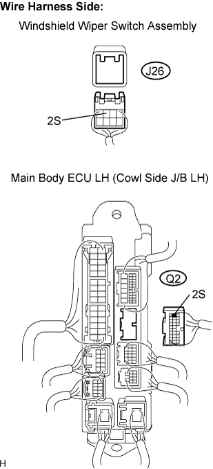
Measure the resistance according to the value(s) in the table below.
- Standard resistance:
Tester Connection
Condition
Specified Condition
J26-3 (2S) - Q2-11 (2S)
Always
Below 1 Ω
Q2-11 (2S) - Body ground
Always
10 kΩ or higher
|
|
||||
| OK | ||
|
||
| ||