SYSTEM DIAGRAM
System information
| WIPER AND WASHER SYSTEM |
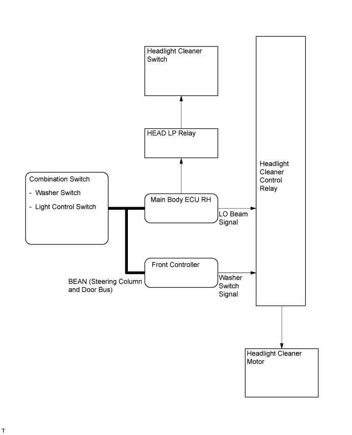
Various switches or sensors are shown as being inputs for the different systems mentioned in the section. Where direct electrical connections do not exist between components, signals may be carried across the different networks (BEAN, CAN) that exist on the vehicle. If a signal needs to travel from the CAN network to the BEAN network, or between different BEAN networks, the Gateway ECU allows the signal to travel between these different networks. Some of these different signals can be confirmed or inspected using the intelligent tester.
The following system diagrams are intended to show the concept of operation, and may not precisely reflect the construction of the system on the vehicle.
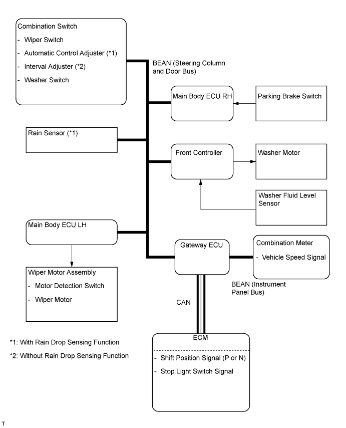

| Transmitting ECU (Transmitter) |
Receiving ECU |
Signals |
Communication |
| Rain Sensor |
Main Body ECU LH (Cowl Side J/B LH) |
|
BEAN |
| Combination Switch ECU |
Main Body ECU LH (Cowl Side J/B LH) |
|
BEAN |
| Combination Switch ECU |
Front Light ECU |
|
BEAN |
| Combination Meter ECU |
Main Body ECU LH (Cowl Side J/B LH) |
|
BEAN |
| Combination Meter ECU |
Rain Sensor |
|
BEAN |
| Combination Switch ECU |
Rain Sensor |
|
BEAN |
| ECM |
Main Body ECU LH (Cowl Side J/B LH) |
|
CAN - BEAN |
| Main Body ECU RH (Cowl Side J/B RH) |
Main Body ECU LH (Cowl Side J/B LH) |
|
BEAN |
| Main Body ECU RH (Cowl Side J/B RH) |
Combination Switch ECU |
|
BEAN |
| Main Body ECU RH (Cowl Side J/B RH) |
Rain Sensor |
|
BEAN |
| Main Body ECU LH (Cowl Side J/B LH) |
Rain Sensor |
|
BEAN |
| Steering Lock ECU |
Rain Sensor |
|
BEAN |
| Front Light ECU |
Combination Meter ECU |
|
BEAN |
- HINT:
- Wiper operation is controlled by the main body ECU LH (cowl side J/B LH).
- The rain sensor controls the auto wiper function.
- Wiper operation is controlled by the main body ECU LH (cowl side J/B LH).