TERMINALS OF ECU
System information
| CHECK ENGINE ROOM NO. 2 R/B (FRONT CONTROLLER) |
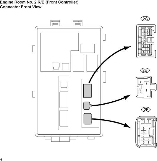

| Symbols (Terminal No.) |
Wiring Color |
Terminal Description |
Condition |
Specified Condition |
| ALTB (2E-1) - Body ground |
W - Body ground |
Power source circuit |
Always |
10 to 14 V |
| BATB (2E-2) - Body ground |
W-L - Body ground |
Power source circuit |
Always |
10 to 14 V |
| FMIG (2E-3) - Body ground |
B-Y - Body ground |
Engine switch signal circuit |
Engine switch on (IG) |
10 to 14 V |
| FMIG (2E-3) - Body ground |
B-Y - Body ground |
Engine switch signal circuit |
Engine switch off |
Below 1 V |
| FMB3 (2E-4) - Body ground |
G-R - Body ground |
Power source circuit |
Always |
10 to 14 V |
| E (2F-1) - Body ground |
W-B - Body ground |
Ground |
Always |
Below 1 V |
| MPX1 (2F-5) - Body ground |
L - Body ground |
Multiplex communication signal circuit |
Engine switch on (IG) |
Signal waveform |
| MPX2 (2F-6) - Body ground |
GR - Body ground |
Multiplex communication signal circuit |
Engine switch on (IG) |
Signal waveform |
| FOGR (2G-6) - Body ground |
LG - Body ground |
Fog light circuit (To front fog light RH) |
Front fog light ON |
10 to 14 V |
| FOGR (2G-6) - Body ground |
LG - Body ground |
Fog light circuit (To front fog light RH) |
Front fog light OFF |
Below 1 V |
| FOGL (2G-7) - Body ground |
G-R - Body ground |
Fog light circuit (To front fog light LH) |
Front fog light ON |
10 to 14 V |
| FOGL (2G-7) - Body ground |
G-R - Body ground |
Fog light circuit (To front fog light LH) |
Front fog light OFF |
Below 1 V |
| CRAR (2G-8) - Body ground |
G -Body ground |
Taillight circuit (To parking light RH) |
Light control switch on TAIL |
10 to 14 V |
| CRAR (2G-8) - Body ground |
G -Body ground |
Taillight circuit (To parking light RH) |
Light control switch OFF |
Below 1 V |
| CRAL (2G-9) - Body ground |
G -Body ground |
Taillight circuit (To parking light LH) |
Light control switch on TAIL |
10 to 14 V |
| CRAL (2G-9) - Body ground |
G -Body ground |
Taillight circuit (To parking light LH) |
Light control switch OFF |
Below 1 V |
| HLHR (2G-12) - Body ground |
R-W -Body ground |
Hi-beam circuit (To headlight RH) |
Headlight dimmer switch on HI |
10 to 14 V |
| HLHR (2G-12) - Body ground |
R-W -Body ground |
Hi-beam circuit (To headlight RH) |
Headlight dimmer switch on HEAD |
Below 1 V |
| HLHL (2G-13) - Body ground |
R-Y -Body ground |
Hi-beam circuit (To headlight LH) |
Headlight dimmer switch on HI |
10 to 14 V |
| HLHL (2G-13) - Body ground |
R-Y -Body ground |
Hi-beam circuit (To headlight LH) |
Headlight dimmer switch on HEAD |
Below 1 V |
| (2G-4) - Body ground |
R-L - Body ground |
Hi-beam circuit |
Headlight dimmer switch on HI |
10 to 14 V |
| (2G-4) - Body ground |
R-L - Body ground |
Hi-beam circuit |
Headlight dimmer switch on HEAD |
Below 1 V |
| (2G-10) - Body ground |
G-Y - Body ground |
Taillight circuit (To marker light RH) |
Light control switch on TAIL |
10 to 14 V |
| (2G-10) - Body ground |
G-Y - Body ground |
Taillight circuit (To marker light RH) |
Light control switch OFF |
Below 1 V |
| (2G-11) - Body ground |
BR - Body ground |
Taillight circuit (To marker light LH) |
Light control switch on TAIL |
10 to 14 V |
| (2G-11) - Body ground |
BR - Body ground |
Taillight circuit (To marker light LH) |
Light control switch OFF |
Below 1 V |
| CHECK MAIN BODY ECU RH (COWL SIDE J/B RH) |
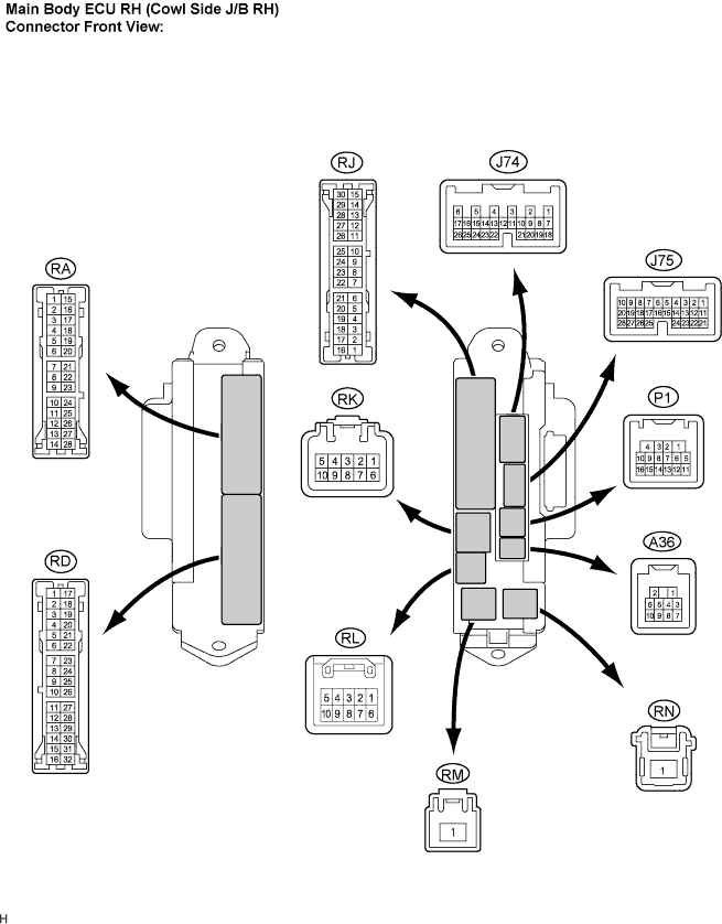
| Symbols (Terminal No.) |
Wiring Color |
Terminal Description |
Condition |
Specified Condition |
| GND2 (RD-7) - Body ground |
W-B - Body ground |
Ground |
Always |
Below 1 V |
| LCTY (RA-11) - Body ground |
BR - Body ground |
Illumination signal (From door courtesy switch rear LH) |
Rear LH door is closed |
10 to 14 V |
| LCTY (RA-11) - Body ground |
BR - Body ground |
Illumination signal (From door courtesy switch rear LH) |
Rear LH door is open |
Below 1 V |
| MPX1 (RJ-21) - Body ground |
GR - Body ground |
Multiplex communication signal circuit |
Engine switch on (IG) |
Signal waveform |
| BECU (RK-5) - Body ground |
G-R - Body ground |
Multiplex communication power source circuit |
Always |
10 to 14 V |
| HRLY (RL-7) - Body ground |
R-W - Body ground |
HEAD signal (To HEAD relay) |
Light control switch OFF or in TAIL |
10 to 14 V |
| HRLY (RL-7) - Body ground |
R-W - Body ground |
HEAD signal (To HEAD relay) |
Light control switch in HEAD |
Below 1 V |
| DCTY (P1-14) - Body ground |
W - Body ground |
Illumination signal (From driver side courtesy switch) |
Driver's side door is closed |
10 to 14 V |
| DCTY (P1-14) - Body ground |
W - Body ground |
Illumination signal (From driver side courtesy switch) |
Driver's side door is open |
Below 1 V |
| RCTY (P1-16) - Body ground |
O - Body ground |
Illumination signal (From door courtesy switch rear RH) |
Rear door RH is closed |
10 to 14 V |
| RCTY (P1-16) - Body ground |
O - Body ground |
Illumination signal (From door courtesy switch rear RH) |
Rear door RH is open |
Below 1 V |
| FSPT (J75-15) - Body ground |
R - Body ground |
Illumination signal (To footwell lights) |
Footwell lights come on |
Below 1 V |
| FSPT (J75-15) - Body ground |
R - Body ground |
Illumination signal (To footwell lights) |
Footwell lights go off |
10 to 14 V |
| MPX2 (J75-21) - Body ground |
GR - Body ground |
Multiplex communication signal circuit |
Engine switch on (IG) |
Signal waveform |
| CLTE (J74-4) - Body ground |
W - Body ground |
Automatic light control sensor ground circuit |
Always |
Below 1 V |
| CLTS (J74-5) - Body ground |
R - Body ground |
Automatic light control sensor ground circuit |
Engine switch off |
Below 1 V |
| CLTS (J74-5) - Body ground |
R - Body ground |
Automatic light control sensor ground circuit |
Engine switch on (IG), light control switch on AUTO, headlight comes ON |
Signal waveform |
| CLTB (J74-6) - Body ground |
GR - Body ground |
Automatic light control sensor power source circuit |
Engine switch off |
Below 1 V |
| CLTB (J74-6) - Body ground |
GR - Body ground |
Automatic light control sensor power source circuit |
Engine switch on (IG) |
10 to 14 V |
| HEAD (J74-23) - Body ground |
L - Body ground |
HEAD signal (From light control switch) |
Light control switch OFF or on TAIL |
10 to 14 V |
| HEAD (J74-23) - Body ground |
L - Body ground |
HEAD signal (From light control switch) |
Light control switch in HEAD |
Below 1 V |
| ALTB (RA-15) - Body ground |
SB - Body ground |
Power source circuit |
Always |
10 to 14 V |
| UL2 (J75-4) - Body ground |
O - Body ground |
Interior light switch )ON / OFF) signal |
Interior light switch ON |
Below 1 V |
| UL2 (J75-4) - Body ground |
O - Body ground |
Interior light switch )ON / OFF) signal |
Interior light switch OFF |
10 to 14 V |
| TRLY (RD-1) - Body ground |
Y - Body ground |
HEAD signal (to HEAD relay) |
Light control switch OFF |
10 to 14 V |
| TRLY (RD-1) - Body ground |
Y - Body ground |
HEAD signal (to HEAD relay) |
Light control switch in TAIL |
Below 1 V |
| PCYL (J75-24) - Body ground |
G - Body ground |
Illumination signal (From door courtesy light front LH) |
Passenger's side door is open |
Below 1 V |
| PCYL (J75-24) - Body ground |
G - Body ground |
Illumination signal (From door courtesy light front LH) |
Passenger's side door is closed |
10 to 14 V |
| DCYL (P1-13) - Body ground |
G - Body ground |
Illumination signal (From door courtesy light front RH) |
Driver's side door is open |
Below 1 V |
| DCYL (P1-13) - Body ground |
G - Body ground |
Illumination signal (From door courtesy light front RH) |
Driver's side door is closed |
10 to 14 V |
| LGCY (J75-25) - Body ground |
L - Body ground |
Illumination signal (From door courtesy switch luggage) |
Luggage door is open |
Below 1 V |
| LGCY (J75-25) - Body ground |
L - Body ground |
Illumination signal (From door courtesy switch luggage) |
Luggage door is closed |
10 to 14 V |
| PCTY (J75-23) - Body ground |
B - Body ground |
Illumination signal (From door courtesy switch front LH) |
Passenger's side door is open |
Below 1 V |
| PCTY (J75-23) - Body ground |
B - Body ground |
Illumination signal (From door courtesy switch front LH) |
Passenger's side door is closed |
10 to 14 V |
| HAZ (J74-2) - Body ground |
Y - Body ground |
HAZARD signal (From HAZARD switch) |
HAZARD switch ON |
Below 1 V |
| HAZ (J74-2) - Body ground |
Y - Body ground |
HAZARD signal (From HAZARD switch) |
HAZARD switch OFF |
10 to 14 V |
| CHECK MAIN BODY ECU LH |
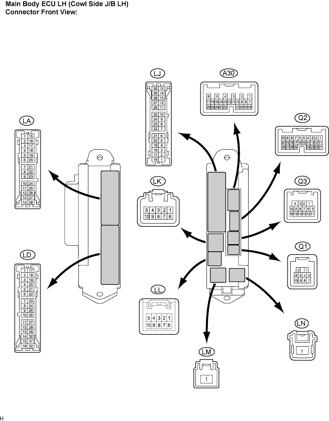
| Symbols (Terminal No.) |
Wiring Color |
Terminal Description |
Condition |
Specified Condition |
| GND (LD-3) - Body ground |
W-B - Body ground |
Ground |
Always |
Below 1 V |
| TR (LA-15) - Body ground |
P - Body ground |
RH side turn signal (To turn signal flasher assembly) |
Engine switch off |
Below 1 V |
| TR (LA-15) - Body ground |
P - Body ground |
RH side turn signal (To turn signal flasher assembly) |
Engine switch on (IG) and turn signal switch (right turn) ON |
10 to 14 V (60 to 120 times per minute) |
| TL (LA-16) - Body ground |
BR - Body ground |
LH side turn signal (To turn signal flasher assembly) |
Engine switch off |
Below 1 V |
| TL (LA-16) - Body ground |
BR - Body ground |
LH side turn signal (To turn signal flasher assembly) |
Engine switch on (IG) and turn signal switch (left turn) ON |
10 to 14 V (60 to 120 times per minute) |
| SGND (LD-8) - Body ground |
W-B - Body ground |
Ground |
Always |
Below 1 V |
| SGND (LD-9) - Body ground |
W-B - Body ground |
Ground |
Always |
Below 1 V |
| MPXB (LD-18) - Body ground |
LG - Body ground |
Multiplex communication power source circuit |
Always |
10 to 14 V |
| ILE (A36-2) - Body ground |
V - Body ground |
Illumination signal (To front interior light) |
Interior light switch in DOOR position and interior lights come on |
Below 1 V |
| ILE (A36-2) - Body ground |
V - Body ground |
Illumination signal (To front interior light) |
Interior light switch in DOOR position and interior lights come on |
10 to 14 V |
| RCTY (Q1-3) - Body ground |
R - Body ground |
Illumination signal (To shift illumination light rear RH) |
Shift illumination comes on |
Below 1 V |
| RCTY (Q1-3) - Body ground |
R - Body ground |
Illumination signal (To shift illumination light rear RH) |
Shift illumination goes off |
10 to 14 V |
| LCTY (Q1-4) - Body ground |
LG - Body ground |
Illumination signal (To door mirror foot lights) |
Door mirror foot light comes on |
10 to 14 V |
| MPX1 (Q3-15) - Body ground |
GR - Body ground |
Multiplex communication signal circuit |
Engine switch on (IG) |
Signal waveform |
| RFRL (LJ-25) - Body ground |
O - Body ground |
RR Foglight signal (to RR Foglight) |
RR Foglight switch in OFF |
10 to 14 V |
| RFRL (LJ-25) - Body ground |
O - Body ground |
RR Foglight signal (to RR Foglight) |
RR Foglight switch in ON |
Below 1 V |
| MPX2 (A30-17) - Body ground |
GR - Body ground |
Multiplex communication signal circuit |
Engin switch on (IG) |
Signal waveform |
| ILE1 (LA-19) - Body ground |
W - Body ground |
Illumination signal (to scuff plate light) |
Room light switch in DOOR position and scuff plate lights comes on |
Below 1 V |
| ILE1 (LA-19) - Body ground |
W - Body ground |
Illumination signal (to scuff plate light) |
Room light switch in DOOR position and scuff plate lights comes off |
10 to 14 V |
| LGCY (Q3-3) - Body ground |
W - Body ground |
Illumination signal (to seat illumination) |
Seat illumination comes on |
Below 1 V |
| LGCY (Q3-3) - Body ground |
W - Body ground |
Illumination signal (to seat illumination) |
Seat illumination comes off |
10 to 14 V |
| BDCY (Q3-11) - Body ground |
P - Body ground |
Interior light switch (Door) signal |
Interior light switch on |
Below 1 V |
| BDCY (Q3-11) - Body ground |
P - Body ground |
Interior light switch (Door) signal |
Interior light switch off |
10 to 14 V |
| CHECK COMBINATION SWITCH ASSEMBLY (Windshield Wiper Switch) |
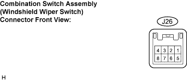
| Symbols (Terminal No.) |
Wiring Color |
Terminal Description |
Condition |
Specified Condition |
| B (J26-1) - E (J26-5) |
LG - W-B |
Power source circuit (From battery) |
Always |
10 to 14 V |
| IG (J26-2) - E (J26-5) |
B - W-B |
Engine switch signal circuit (From engine switch) |
Engine switch off |
Below 1 V |
| IG (J26-2) - E (J26-5) |
B - W-B |
Engine switch signal circuit (From engine switch) |
Engine switch on (IG) |
10 to 14 V |
| HEAD (J26-4) - Body ground |
L - Body ground |
Light control switch HEAD signal |
Light control switch not on HEAD |
10 to 14 V |
| HEAD (J26-4) - Body ground |
L - Body ground |
Light control switch HEAD signal |
Light control switch on HEAD |
Below 1 V |
| E (J26-5) - Body ground |
W-B - Body ground |
Ground |
Always |
Below 1 V |
| MPX1 (J26-6) - Body ground |
GR - Body ground |
Multiplex communication signal circuit |
Engine switch on (IG) |
Signal waveform |
| MPX2 (J26-7) - Body ground |
GR - Body ground |
Multiplex communication signal circuit |
Engine switch on (IG) |
Signal waveform |
| CHECK OVERHEAD J/B |
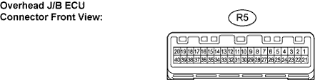
| Symbols (Terminal No.) |
Wiring Color |
Terminal Description |
Condition |
Specified Condition |
| +B1 (R5-1) - Body ground |
L - Body ground |
Power source circuit |
Always |
10 to 14 V |
| RRMP (R5-3) - Body ground |
O - Body ground |
Rear personal light power source circuit |
Always |
10 to 14 V |
| ILLB (R5-4) - Body ground |
L - Body ground |
Rear interior light power source circuit |
Always |
10 to 14 V |
| CTY (R5-12) - Body ground |
W - Body ground |
Seat illumination light circuit |
Seat illumination light comes off |
10 to 14 V |
| CTY (R5-12) - Body ground |
W - Body ground |
Seat illumination light circuit |
Seat illumination light comes on |
Below 1 V |
| ILL (R5-13) - Body ground |
BR - Body ground |
Interior light circuit |
Interior light comes off |
10 to 14 V |
| ILL (R5-13) - Body ground |
BR - Body ground |
Interior light circuit |
Interior light comes on |
Below 1 V |
| SHFT (R5-14) - Body ground |
Y - Body ground |
Shift illumination circuit |
Shift illumination comes off |
10 to 14 V |
| SHFT (R5-14) - Body ground |
Y - Body ground |
Shift illumination circuit |
Shift illumination comes on |
Below 1 V |
| GND3 (R5-18) - Body ground |
W-B - Body ground |
Ground |
Always |
Below 1 V |
| RGND (R5-19) - GND3 (R5-18) |
W-B - W-B |
Interior light ground |
Always |
Below 1 V |
| LILL (R5-32) - CTY (R5-12) |
B - W |
Seat illumination circuit |
Always |
Below 1 Ω |
| RILL (R5-33) - ILL (R5-13) |
P - BR |
Interior light circuit |
Always |
Below 1 Ω |
| CILL (R5-34) - GND3 (R5-18) |
P - W-B |
Interior light switch (ON/OFF) circuit |
Interior light switch off |
10 to 14 V |
| CILL (R5-34) - GND3 (R5-18) |
P - W-B |
Interior light switch (ON/OFF) circuit |
Interior light switch on |
Below 1 V |
| DOOR (R5-35) - GND3 (R5-18) |
G - W-B |
Interior light switch (DOOR) circuit |
Interior light switch off |
10 to 14 V |
| DOOR (R5-35) - GND3 (R5-18) |
G - W-B |
Interior light switch (DOOR) circuit |
Interior light switch on |
Below 1 V |
| CHECK AFS ECU |
*2: LHD
*3: With AFS
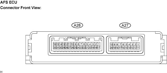
| Symbols (Terminal No.) |
Wiring Color |
Terminal Description |
Condition |
Specified Condition |
| SBF (A28-1) - SGF (A28-17) |
R-B - G-R |
Vehicle height signal (To height control sensor) |
Engine switch off |
Below 1 V |
| Engine switch on (IG) |
4.5 V to 5.5 V |
|||
| SPDL (A28-6) - E1 (A27-1) |
P-B - W-B *1 R-L - W-B *2 |
Vehicle speed signal (To skid control ECU) |
Vehicle is driving at approx. 30 km/h (19 mph) |
Pulse generation (see waveform 1) |
| SPDR (A28-7) - E1 (A27-1) |
G-W - W-B |
Vehicle speed signal (To skid control ECU) |
Vehicle is driving at approx. 30 km/h (19 mph) |
Pulse generation (see waveform 1) |
| BR1+ (A28-9) - BR1- (A28-10) |
LG-R - O |
Headlight swivel motor RH |
Engine switch off |
Below 1 V |
| Engine running, light control switch in HEAD, driving at more than 10 km/h (6 mph) and turning the steering wheel to right more than 7.5° |
Pulse generation (see waveform 2) |
|||
| BR2+ (A28-11) - BR2- (A28-12) |
L-B - L-Y |
Headlight swivel motor RH |
Engine Switch off |
Below 1 V |
| Engine running, light control switch in HEAD, driving at more than 10 km/h (6 mph) and turning the steering wheel more than 7.5° |
Pulse generation (see waveform 2) |
|||
| LR1+ (A28-13) - LR1- (A28-14) |
L - BR-W |
Headlight leveling actuator RH |
Engine Switch off |
Below 1 V |
| Engine running, light control switch in HEAD, the vehicle is standing still or bounding |
Pulse generation (see waveform 3) |
|||
| LR2+ (A28-15) - LR2- (A28-16) |
P - LG |
Headlight leveling actuator RH |
Engine Switch off |
Below 1 V |
| Engine running, light control switch in HEAD, the vehicle is standing still or bounding |
Pulse generation (see waveform 3) |
|||
| SGF (A28-17) - E1 (A27-1) |
G - R |
Vehicle height signal (To height control sensor) |
Always |
Below 1 V |
| SMGR (A28-18) - E1 (A27-1) |
W-R - W-B |
Headlight swivel motor RH |
Always |
Below 1 V |
| SMGL (A28-19) - E1 (A27-1) |
P-G - W-B |
Headlight swivel motor LH |
Always |
Below 1 V |
| SMBR (A28-21) - SMGR (A28-18) |
GR - W-R |
Headlight swivel motor RH |
Engine switch off |
Below 1 V |
| Engine switch on (IG) |
4.5 V to 5.5 V |
|||
| SMBL (A28-22) - SMGL (A28-19) |
W - P-G |
Headlight swivel motor LH |
Engine switch off |
Below 1 V |
| Engine switch on (IG) |
4.5 V to 5.5 V |
|||
| SMR (A28-23) - SMGR (A28-18) |
G-B - W-R |
Headlight swivel motor RH |
Engine switch off |
Below 1 V |
| Engine switch on (IG) |
0.3 V to 4.6 V |
|||
| SML (A28-24) - SMGL (A28-19) |
Y-B - P-G |
Headlight swivel motor LH |
Engine switch off |
Below 1 V |
| Engine switch on (IG) |
0.3 V to 4.6V |
|||
| BL1+ (A28-25) - BL1-(A28-26) |
B-L - L-W |
Headlight swivel motor LH |
Engine switch off |
Below 1 V |
| Engine running, light control switch in HEAD, driving at more than 10 km/h (6 mph) and turning the steering wheel to left more than 7.5° |
Pulse generation (see waveform 2) |
|||
| BL2+ (A28-27) - BL2-(A28-28) |
L-R - B-Y |
Headlight swivel motor LH |
Engine Switch off |
Below 1 V |
| Engine running, light control switch in HEAD, driving at more than 10 km/h (6 mph) and turning the steering wheel to left more than 7.5° |
Pulse generation (see waveform 2) |
|||
| LL1+ (A28-29) - LL1-(A28-30) |
R-G - G |
Headlight leveling actuator LH |
Engine Switch off |
Below 1 V |
| Engine running, light control switch in HEAD, the vehicle is still or bounced |
Pulse generation (see waveform 3) |
|||
| LL2+ (A28-31) - LL2-(A28-32) |
Y-R - V-R |
Headlight leveling actuator LH |
Engine switch off |
Below 1 V |
| Engine running, light control switch in HEAD, the vehicle is still or bounced |
Pulse generation (see waveform 3) |
|||
| E1 (A27-1) - Body ground |
W-B - Body ground |
Ground |
Always |
Below 1 V |
| IG (A27-2) - E1 (A27-1) |
B-O - W-B |
Power source circuit (To engine switch) |
Engine switch off |
Below 1 V |
| Engine switch on (IG) |
10 to 14 V |
|||
| MPX1 (A27-5) - E1 (A27-1) |
BR - W-B *3 |
Multiplex communication signal |
Engine switch on (IG) |
Signal waveform |
| MPX2 (A27-6) - E1 (A27-1) |
BR-B - W-B *3 |
Multiplex communication signal |
Engine switch on (IG) |
Signal waveform |
| SS+ (A27-7) -SS- (A27-8) |
L - LG |
Steering sensor signal (To position sensor) |
Engine idling, slowly turn steering wheel |
Pulse generation |
| SHRL (A27-9) - SGR (A27-20) |
B-W - R-Y |
Vehicle height signal (To height control sensor rear) |
Engine switch off |
Below 1 V |
| Engine switch on (IG) , bouncing the vehicle |
0.5 to 4.5 V |
|||
| SHFL (A28-2) - SGF (A28-17) |
G-Y - G-R |
Vehicle height signal (To height control sensor front) |
Engine Switch off |
Below 1 V |
| Engine Switch on (IG) , bouncing the vehicle |
0.5 to 4.5 V |
|||
| SBR (A27-10) - SGR (A27-20) |
W - R-Y |
Vehicle height signal (To height control sensor rear) |
Engine switch off |
Below 1 V |
| Engine switch on (IG) |
4.5 to 5.5 V |
|||
| SBF (A28-1) - SGF (A28-17) |
R-B - G-R |
Vehicle height signal (To height control sensor front) |
Engine switch off |
Below 1 V |
| Engine switch on (IG) |
4.5 to 5.5 V |
Waveform 1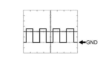
Item
Contents
Terminal
SPDL - GND
SPDR - GND
Tool setting
5 V/DIV., 2 ms./DIV.
Vehicle condition
Vehicle is driving at approximately 30 km/h (19 mph)
Waveform 2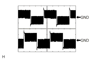
Item
Contents
Terminal
BL1+ - BL1-
BL2+ - BL2-
BR1+ - BR1-
BR2+ - BR2-
Tool setting
10 V/DIV., 5 ms./DIV.
Vehicle condition
- Engine running, light control switch in HEAD, driving at more than 10 km/h (6 mph) and turning the steering wheel more than 7.5°
- If the value is not within the standard range, it is possible there is some defect on the vehicle side. Inspect the fuse, wire harness and connector.
- Engine running, light control switch in HEAD, driving at more than 10 km/h (6 mph) and turning the steering wheel more than 7.5°
Waveform 3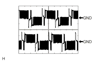
Item
Contents
Terminal
LR1+ - LR1-
LR2+ - LR2-
LL1+ - LL1-
LL2+ - LL2-
Tool setting
10 V/DIV., 5 ms./DIV.
Vehicle condition
- Engine running, light control switch in HEAD, driving at more than 10 km/h (6 mph) and turning the steering wheel more than 7.5°
- If the value is not within the standard range, it is possible there is some defect on the vehicle side. Inspect the fuse, wire harness and connector.
- Engine running, light control switch in HEAD, driving at more than 10 km/h (6 mph) and turning the steering wheel more than 7.5°