REMOVAL
Removal / installation
| 1. REMOVE COOL AIR INTAKE DUCT SEAL |

Remove the 11 clips and intake duct seal.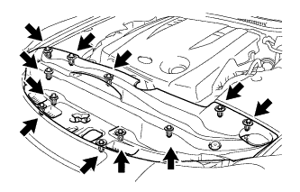

| 2. REMOVE ENGINE ROOM SIDE COVER LH |
Remove the 5 clips and side cover.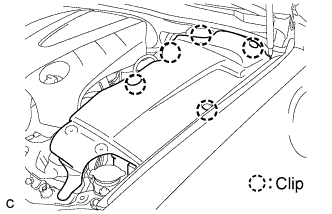
| 3. REMOVE ENGINE ROOM SIDE COVER RH |
Remove the 2 clips and side cover.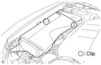
| 4. REMOVE V-BANK COVER SUB-ASSEMBLY |
Raise the V-bank cover to disengage the clip on the rear of the cover. Raise the cover again to disengage the 2 clips on the front of the cover and remove the cover.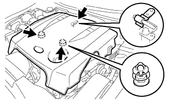
- NOTICE:
- Attempting to disengage both front and rear clips at the same time may cause the cover to break.
| 5. REMOVE FRONT FENDER PROTECTOR UPPER LH |
Using a clip remover, separate the clip on the rubber portion of the cowl top ventilator louver sub-assembly from the front upper fender protector LH.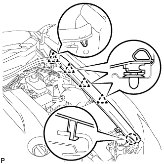
Disengage the 3 clips and the claw to remove the front fender protector upper LH.
| 6. REMOVE FRONT FENDER PROTECTOR UPPER RH |
- HINT:
- Removal procedure of the RH side is the same as that of the LH side.
| 7. REMOVE ROOF DRIP SIDE FINISH MOULDING LH |
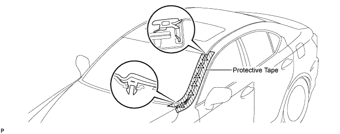
Put protective tape around the roof drip side finish moulding.
Using a moulding remover, disengage the 6 clips and remove the roof drip side finish moulding.
- NOTICE:
- Do not remove the clips.
- If the clips are damaged or fall off, replace them with new clips.
- Do not remove the clips.
| 8. REMOVE ROOF DRIP SIDE FINISH MOULDING RH |
- HINT:
- Removal procedure of the RH side is the same as that of the LH side.
| 9. REMOVE FRONT WIPER ARM HEAD CAP |
Using a screwdriver, remove the front wiper arm head cap.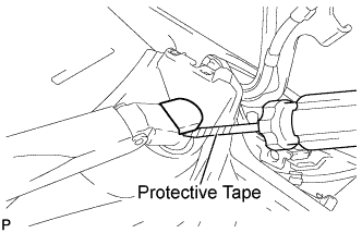
- HINT:
- Use the same procedures for the RH side and the LH side.
- Tape the screwdriver tip before use.
- Use the same procedures for the RH side and the LH side.
| 10. REMOVE WINDSHIELD WIPER ARM AND BLADE ASSEMBLY LH |
Remove the nut and the front wiper arm and blade assembly LH.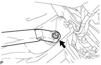
| 11. REMOVE WINDSHIELD WIPER ARM AND BLADE ASSEMBLY RH |
Remove the nut and the front wiper arm and blade assembly RH.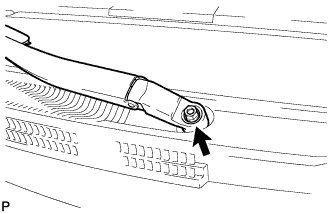
| 12. REMOVE COWL TOP VENTILATOR LOUVER SUB-ASSEMBLY |
Remove the 2 clips.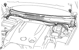
Disengage the 11 claws, and pull out the cowl top ventilator louver sub-assembly.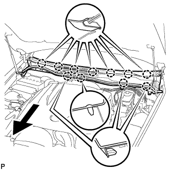
| 13. DRAIN ENGINE COOLANT |
- NOTICE:
- Do not remove the radiator cap while the engine and radiator are still hot. Pressurized, hot engine coolant and steam may be released and cause serious burns.
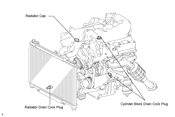
Remove the radiator cap and reservoir tank cap.
Loosen the radiator drain cock plug and 2 cylinder block drain cock plugs. Then drain the coolant.
- HINT:
- Collect the coolant in a container and dispose of it according to the regulations in your area.
| 14. DISCONNECT NO. 2 VENTILATION HOSE |
Disconnect the ventilation hose from the cylinder head.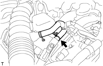
| 15. REMOVE AIR CLEANER CAP WITH AIR CLEANER HOSE |
Disconnect the MAF meter connector.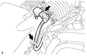
Disconnect the clamp from the air cleaner.
Disconnect the VSV hose.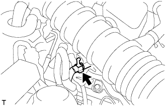
Disconnect the 4 clamps.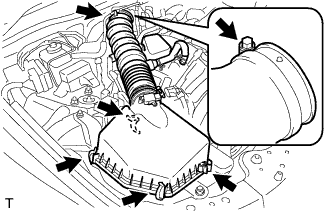
Remove the hose clamp and air cleaner cap with air cleaner hose.
| 16. REMOVE THROTTLE BODY |
Disconnect the throttle motor connector.
Remove the 4 bolts and disconnect the throttle body from the intake air surge tank.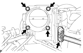
Disconnect the 2 water by-pass hoses from the throttle body.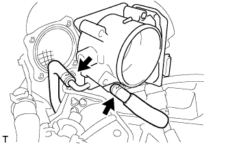
Remove the throttle body and gasket.
| 17. REMOVE INTAKE AIR SURGE TANK ASSEMBLY |
Disconnect the vacuum hose from the intake air surge tank.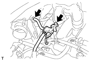
Remove the bolt and disconnect the No. 1 vacuum switching valve assembly from the intake air surge tank.
Disconnect the wire harness and hose from the surge tank.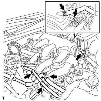
Disconnect the ventilation hose from the intake air surge tank.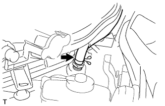
Remove the bolt and water hose joint from the intake air surge tank.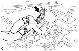
Remove the bolt and disconnect the surge tank stay.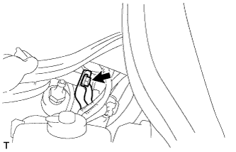
Using a 5 mm hexagon socket wrench, remove the 7 bolts, 2 nuts and gasket.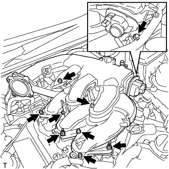
| 18. REMOVE INTAKE MANIFOLD |
Disconnect the connector for the SCV.
Disconnect the SCV position sensor connector.
Remove the 4 bolts, 4 nuts, intake manifold and gasket.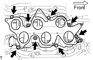
| 19. REMOVE ENGINE COOLANT TEMPERATURE SENSOR |
Disconnect the engine coolant temperature sensor connector.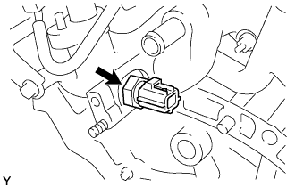
Remove the engine coolant temperature sensor.
Remove the gasket from the engine coolant temperature sensor.