INSTALLATION
Removal / installation
| 1. INSTALL HEATED OXYGEN SENSOR |

Using SST, install the heated oxygen sensor.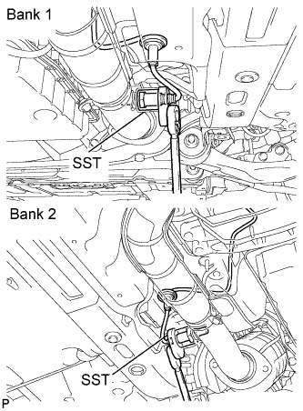

- SST
- 09224-00010
Pass the heated oxygen sensor connector through the floor panel and install the grommet.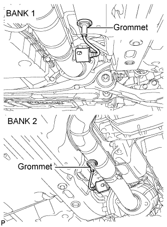
| 2. CONNECT HEATED OXYGEN SENSOR CONNECTOR |
Connect the heated oxygen sensor.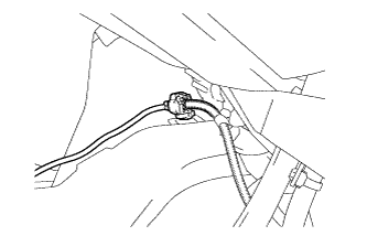
Connect the heated oxygen sensor.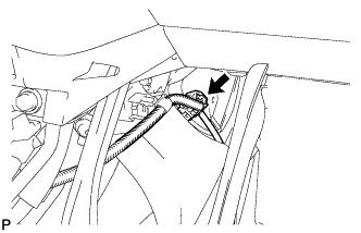
| 3. INSTALL CENTER LOWER INSTRUMENT CLUSTER FINISH PANEL |
Engage the 4 claws and install the center lower instrument cluster finish panel.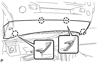
| 4. INSTALL CONSOLE BOX |
Engage the 2 claws and 2 clips.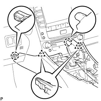
Install the 2 bolts <C>.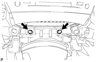
Install the 2 bolts <C>.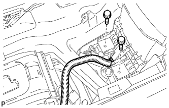
Connect the connector.
Connect the connectors.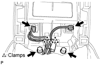
Engage the 2 clamps.
Install the 2 bolts <C>.
| 5. INSTALL CONSOLE BOX REGISTER ASSEMBLY |
Engage the 2 claws and 4 clips, and then install the console box register assembly.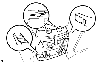
Install the rear ash receptacle assembly.
| 6. INSTALL FRONT ASH RECEPTACLE SUB-ASSEMBLY |
Connect the connectors.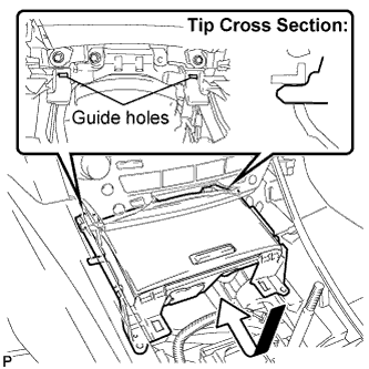
Insert the protruding parts of the front ash receptacle sub-assembly into the 2 guide holes as shown in the illustration.
Install the front ash receptacle sub-assembly with the 2 screws <F>.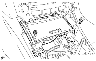
| 7. INSTALL FRONT CONSOLE PANEL SUB-ASSEMBLY (for Manual Transmission) |
Engage the 6 clips.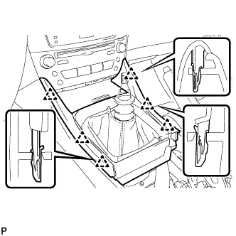
Close the snap.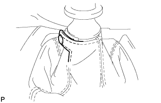
| 8. INSTALL REAR CONSOLE PANEL SUB-ASSEMBLY (for Manual Transmission) |
Engage the 7 claws and 2 clips.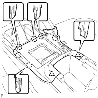
Close the snap.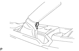
| 9. INSTALL CONSOLE PANEL SUB-ASSEMBLY (for Automatic Transmission) |
Connect the connectors.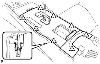
Engage the 8 clips and install the console panel sub-assembly.
| 10. INSTALL UPPER CONSOLE PANEL NO. 2 GARNISH (for Automatic Transmission) |
Engage the claw and 2 clips, and then install the upper No. 2 console panel garnish.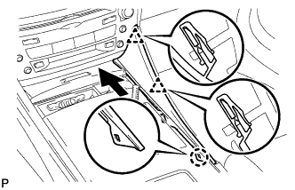
| 11. INSTALL UPPER CONSOLE PANEL NO. 1 GARNISH (for Automatic Transmission) |
Engage the claw and 2 clips, and then install the upper No. 1 console panel garnish.
| 12. INSTALL SHIFT LEVER KNOB SUB-ASSEMBLY (for Manual Transmission) |
| 13. INSTALL SHIFT LEVER KNOB SUB-ASSEMBLY (for Automatic Transmission) |
| 14. CONNECT CABLE TO NEGATIVE BATTERY TERMINAL |
| 15. PERFORM INITIALIZATION |
Perform initialization (Click here).
- NOTICE:
- Certain systems need to be initialized after reconnecting the cable to the negative (-) battery terminal.