TERMINALS OF ECU
System information
| CHECK ENGINE SWITCH |
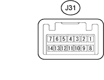

Disconnect the J31 switch connector.
Measure the resistance of the wire harness.
Symbols (Terminal No.)
Wiring Color
Terminal Description
Condition
Specified Condition
AGND (J31-8) - Body ground
GR - Body ground
Ground
Always
Below 1 Ω
- If the result is not as specified, there may be a malfunction on the wire harness side.
- If the result is not as specified, there may be a malfunction on the wire harness side.
Reconnect the J31 switch connector.
Measure the resistance and voltage at the connector.
Symbols (Terminal No.)
Wiring Color
Terminal Description
Condition
Specified Condition
AGND (J31-8) - Body ground
GR - Body ground
Ground
Always
Below 1 Ω
VC5 (J31-14) - AGND (J31-8)
R - GR
Power supply
Key is not in cabin
Below 1 V
VC5 (J31-14) - AGND (J31-8)
R - GR
Power supply
Press engine switch
4.6 to 5.4 V
CODE (J31-10) - AGND (J31-8)
SB - GR
Demodulated signal of key code data
Key is not in cabin
Below 1 V
CODE (J31-10) - AGND (J31-8)
SB - GR
Demodulated signal of key code data
Press engine switch and hold key close to engine switch*
Pulse generation
(see waveform 1)
TXCT (J31-9) - AGND (J31-8)
L - GR
Key code output signal
Key is not in cabin
Below 1 V
TXCT (J31-9) - AGND (J31-8)
L - GR
Key code output signal
Press engine switch and hold key close to engine switch*
Pulse generation
(see waveform 2)
- HINT:
- *: Remove the key battery before performing this inspection.
- If the result is not as specified, the switch may have a malfunction.
Inspect using an oscilloscope.
Waveform 1 (Reference)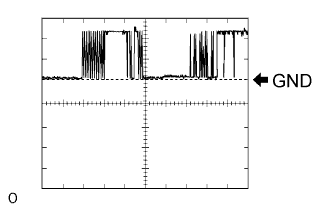
Item
Content
Symbols (Terminal No.)
CODE (J31-10) - AGND (J31-8)
Tool Setting
2 V/DIV., 20 msec./DIV.
Condition
Press engine switch and hold key close to engine switch*
- HINT:
- *: Remove the key battery before performing this inspection.
Waveform 2 (Reference)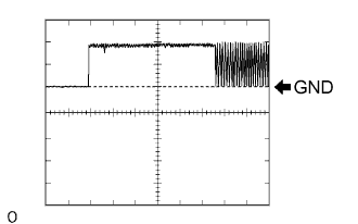
Item
Content
Symbols (Terminal No.)
TXCT (J31-9) - AGND (J31-8)
Tool Setting
2 V/DIV., 20 msec./DIV.
Condition
Press engine switch and hold key close to engine switch*
- HINT:
- *: Remove the key battery before performing this inspection.
| CHECK CERTIFICATION ECU |
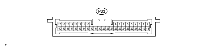
Disconnect the P33 ECU connector.
Measure the resistance and voltage at the wire harness side connector.
Symbols (Terminal No.)
Wiring Color
Terminal Description
Condition
Specified Condition
E (P33-17) - Body ground
W-B - Body ground
Ground
Always
Below 1 Ω
+B1 (P33-1) - E (P33-17)
L - W-B
+B power supply
Always
10 to 14 V
IG (P33-18) - E (P33-17)
B - W-B
Ignition power supply
Engine switch off
Below 1 V
- If the result is not as specified, there may be a malfunction on the wire harness side.
- If the result is not as specified, there may be a malfunction on the wire harness side.
Reconnect the P33 ECU connector.
Measure the resistance and voltage of the connector.
Symbols (Terminal No.)
Wiring Color
Terminal Description
Condition
Specified Condition
AGND (P33-40) - Body ground
LG - Body ground
Engine switch ground
Always
Below 1 Ω
VC5 (P33-30) - AGND (P33-40)
L - LG
Engine switch power supply
Key is not in cabin
Below 1 V
VC5 (P33-30) - AGND (P33-40)
L - LG
Engine switch power supply
Press engine switch
4.6 to 5.4 V
CODE (P33-9) - AGND (P33-40)
GR - LG
Engine switch CODE input
Key is not in cabin
Below 1 V
CODE (P33-9) - AGND (P33-40)
GR - LG
Engine switch CODE input
Press engine switch and hold key close to engine switch*
Pulse generation
(see waveform 1)
TXCT (P33-8) - AGND (P33-40)
G - LG
Engine switch TX output
Key is not in cabin
Below 1 V
TXCT (P33-8) - AGND (P33-40)
G - LG
Engine switch TX output
Press engine switch and hold key close to engine switch*
Pulse generation
(see waveform 2)
- HINT:
- *: Remove the key battery before performing this inspection.
- If the result is not as specified, the ECU may have a malfunction.
Inspect using an oscilloscope.
Waveform 1 (Reference)
Item
Content
Symbols (Terminal No.)
CODE (P33-9) - AGND (P33-40)
Tool Setting
2 V/DIV., 20 msec./DIV.
Condition
Press engine switch and hold key close to engine switch*
- HINT:
- *: Remove the key battery before performing this inspection.
Waveform 2 (Reference)
Item
Content
Symbols (Terminal No.)
TXCT (P33-8) - AGND (P33-40)
Tool Setting
2 V/DIV., 20 msec./DIV.
Condition
Press engine switch and hold key close to engine switch*
- HINT:
- *: Remove the key battery before performing this inspection.
| CHECK ID CODE BOX |

Disconnect the J69 ECU connector.
Measure the resistance and voltage at the wire harness side connector.
Symbols (Terminal No.)
Wiring Color
Terminal Description
Condition
Specified Condition
GND (J69-8) - Body ground
W-B - Body ground
Ground
Always
Below 1 Ω
+B (J69-1) - GND (J69-8)
G - W-B
+B power supply
Always
10 to 14 V
- If the result is not as specified, there may be a malfunction on the wire harness side.
- If the result is not as specified, there may be a malfunction on the wire harness side.
Reconnect the J69 ECU connector.
Measure the voltage of the connector.
Symbols (Terminal No.)
Wiring Color
Terminal Description
Condition
Specified Condition
EFII (J69-5) - GND (J69-8)
W - W-B
ECM input signal
Engine switch off
Below 1 V
EFII (J69-5) - GND (J69-8)
W - W-B
ECM input signal
Engine switch on (IG)
Pulse generation (see waveform 1)
EFIO (J69-6) - GND (J69-8)
P - W-B
ECM output signal
Engine switch off
Below 1 V
EFIO (J69-6) - GND (J69-8)
P - W-B
ECM output signal
Engine switch on (IG)
Pulse generation (see waveform 2)
- If the result is not as specified, the ECU may have a malfunction.
- If the result is not as specified, the ECU may have a malfunction.
Inspect using an oscilloscope.
Waveform 1 (Reference)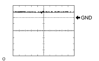
Item
Content
Symbols (Terminal No.)
EFII (J69-5) - GND (J69-8)
Tool Setting
10 V/DIV., 100 msec./DIV.
Condition
Engine switch on (IG)
Waveform 2 (Reference)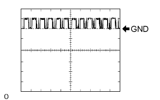
Item
Content
Symbols (Terminal No.)
EFIO (J69-6) - GND (J69-8)
Tool Setting
10 V/DIV., 100 msec./DIV.
Condition
Engine switch on (IG)
| CHECK POWER SOURCE CONTROL ECU |

Disconnect the J55 ECU connector.
Measure the resistance and voltage at the wire harness side connector.
Symbols (Terminal No.)
Wiring Color
Terminal Description
Condition
Specified Condition
GND2 (J55-6) - Body ground
W-B - Body ground
Ground
Always
Below 1 Ω
AM2 (J55-12) - Body ground
O - Body ground
+B power supply
Always
10 to 14 V
AM1 (J55-33) - Body ground
O - Body ground
+B power supply
Always
10 to 14 V
- If the result is not as specified, there may be a malfunction on the wire harness side.
- If the result is not as specified, there may be a malfunction on the wire harness side.
| CHECK STEERING CONTROL ECU |

Disconnect the J29 ECU connector.
Measure the resistance and voltage at the wire harness side connector.
Symbols (Terminal No.)
Wiring Color
Terminal Description
Condition
Specified Condition
SGND (J29-2) - Body ground
W-B - Body ground
Ground
Always
Below 1 Ω
GND (J29-1) - Body ground
W-B - Body ground
Ground
Always
Below 1 Ω
B (J29-7) - Body ground
O - Body ground
+B power supply
Always
10 to 14 V
IG2 (J29-6) - Body ground
LG - Body ground
Ignition power supply
Engine switch off
Below 1 V
IG2 (J29-6) - Body ground
LG - Body ground
Ignition power supply
Engine switch on (IG)
10 to 14 V
- If the result is not as specified, there may be a malfunction on the wire harness side.
- If the result is not as specified, there may be a malfunction on the wire harness side.
| CHECK ECM |
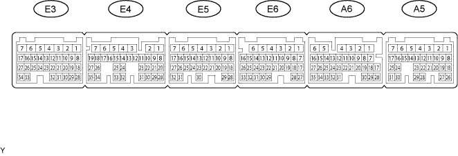
Measure the resistance and voltage of the connector.
Symbols (Terminal No.)
Wiring Color
Terminal Description
Condition
Specified Condition
E1 (E4-7) - Body ground
W-B - Body ground
Ground
Always
Below 1 Ω
E01 (E5-2) - Body ground
W-B - Body ground
Ground
Always
Below 1 Ω
E02 (E5-1) - Body ground
W-B - Body ground
Ground
Always
Below 1 Ω
E03 (E3-6) - Body ground
W-B - Body ground
Ground
Always
Below 1 Ω
E04 (E6-5) - Body ground
W-B - Body ground
Ground
Always
Below 1 Ω
E05 (E6-3) - Body ground
W-B - Body ground
Ground
Always
Below 1 Ω
EC (A5-2) - Body ground
W-B - Body ground
Ground
Always
Below 1 Ω
ME01 (E3-4) - Body ground
W-B - Body ground
Ground
Always
Below 1 Ω
BATT (A5-4) - E1 (E4-7)
L - BR
Battery (for measuring battery voltage and for ECM memory)
Always
10 to 14 V
+B (A5-6) - E1 (E4-7)
B-R - BR
Power source of ECM
Engine switch off
Below 1 V
+B (A5-6) - E1 (E4-7)
B-R - BR
Power source of ECM
Engine switch on (IG)
10 to 14 V
+B1 (A5-5) - E1 (E4-7)
B-R - BR
Power source of ECM
Engine switch off
Below 1 V
+B1 (A5-5) - E1 (E4-7)
B-R - BR
Power source of ECM
Engine switch on (IG)
10 to 14 V
IMI (A6-6) - E1 (E4-7)
LG - BR
Immobiliser code ECU input signal
Engine switch off
Below 1 V
IMI (A6-6) - E1 (E4-7)
LG - BR
Immobiliser code ECU input signal
Engine switch on (IG)
Pulse generation (see waveform 1)
IMO (A6-7) - E1 (E4-7)
W-R - BR
Immobiliser code ECU output signal
Engine switch off
Below 1 V
IMO (A6-7) - E1 (E4-7)
W-R - BR
Immobiliser code ECU output signal
Engine switch on (IG)
Pulse generation (see waveform 2)
- If the result is not as specified, the ECM may have a malfunction.
- If the result is not as specified, the ECM may have a malfunction.
Inspect using an oscilloscope.
Waveform 1 (Reference)
Item
Content
Symbols (Terminal No.)
IMI (A6-6) - E1 (E4-7)
Tool Setting
10 V/DIV., 100 msec./DIV.
Condition
Engine switch on (IG)
Waveform 2 (Reference)
Item
Content
Symbols (Terminal No.)
IMO (A6-7) - E1 (E4-7)
Tool Setting
10 V/DIV., 100 msec./DIV.
Condition
Engine switch on (IG)
| CHECK MAIN BODY ECU RH (COWL SIDE J/B RH) |
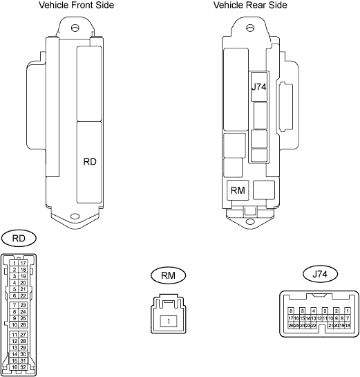
Disconnect the RD and RM junction block connectors.
Measure the resistance and voltage at the wire harness side connectors.
Symbols (Terminal No.)
Wiring Color
Terminal Description
Condition
Specified Condition
GND2 (RD-7) - Body ground
W-B - Body ground
Ground
Always
Below 1 Ω
IG (RM-1) - Body ground
B - Body ground
Ignition power supply
Engine switch off
Below 1 V
IG (RM-1) - Body ground
B - Body ground
Ignition power supply
Engine switch on (IG)
10 to 14 V
- If the result is not as specified, there may be a malfunction on the wire harness side.
- If the result is not as specified, there may be a malfunction on the wire harness side.
Reconnect the RD and RM junction block connectors.
Measure the voltage of the connector.
Symbols (Terminal No.)
Wiring Color
Terminal Description
Condition
Specified Condition
IND (J74-24) - Body ground
LG - Body ground
Indicator light signal
Key is not in cabin (immobiliser system is not set)
Alternating between 10 to 14 V (0.2 seconds) and below 1 V
- If the result is not as specified, the main body ECU RH (cowl side J/B RH) may have a malfunction.
- If the result is not as specified, the main body ECU RH (cowl side J/B RH) may have a malfunction.