INSTALLATION
Removal / installation
| 1. INSTALL IGNITION COIL ASSEMBLY |

Install the 6 ignition coils with the 6 bolts.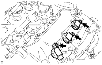

- Torque:
- 10 N*m{ 102 kgf*cm , 7 ft.*lbf }
Connect the 6 ignition coil connectors.
| 2. INSTALL INTAKE AIR SURGE TANK ASSEMBLY |
Install a new gasket to the intake air surge tank.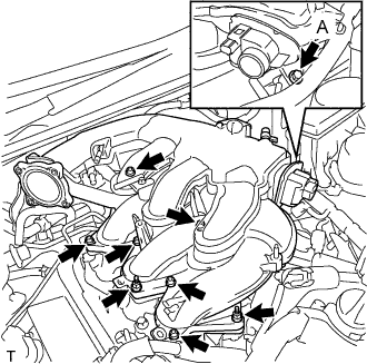
Using a 5 mm hexagon socket wrench, install the 6 bolts.
- Torque:
- Bolts except A:
- 18 N*m{ 184 kgf*cm , 13 ft.*lbf }
Install the bolt and 2 nuts to the intake air surge tank.
- Torque:
- Bolt A:
- 21 N*m{ 214 kgf*cm , 15 ft.*lbf }
- Nut:
- 16 N*m{ 163 kgf*cm , 12 ft.*lbf }
Install the surge tank stay to the intake air surge tank.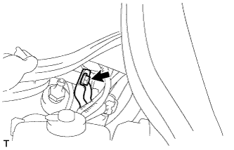
- Torque:
- 21 N*m{ 214 kgf*cm , 15 ft.*lbf }
Connect the water hose joint with the bolt.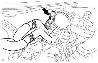
- Torque:
- 10 N*m{ 102 kgf*cm , 7 ft.*lbf }
Connect the ventilation hose to the intake air surge tank.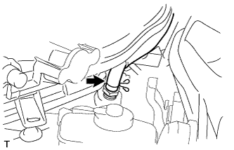
Connect the wire harness and hose to the intake air surge tank.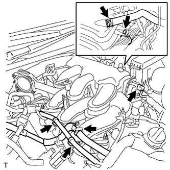
Connect the No. 1 vacuum switching valve assembly to the intake air surge tank.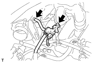
- Torque:
- 18 N*m{ 184 kgf*cm , 13 ft.*lbf }
Connect the vacuum hose to the intake air surge tank.
| 3. INSTALL AIR CLEANER CAP WITH AIR CLEANER HOSE |
Install the air cleaner cap with air cleaner hose assembly with the 4 clamps and hose clamp.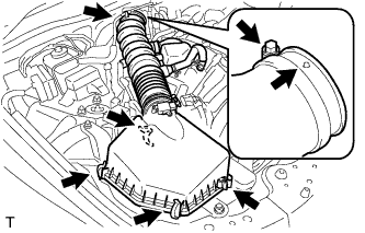
- HINT:
- Be sure to install the air cleaner assembly so that the screw part of the hose clamp is as shown in the illustration.
Install the VSV hose to the air cleaner hose.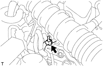
Connect the MAF meter connector and clamp to the air cleaner.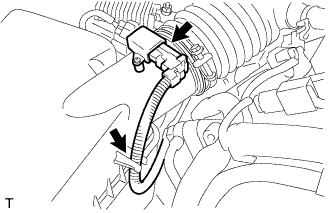
| 4. INSTALL NO. 2 VENTILATION HOSE |
Connect the ventilation hose to the cylinder head cover with the clamp.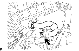
| 5. INSTALL ENGINE ROOM SIDE COVER LH |
Install the side cover with the 5 clips.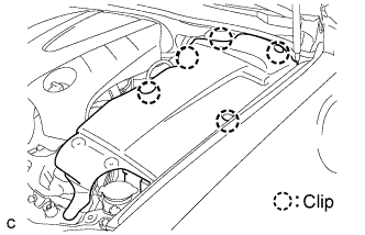
| 6. INSTALL ENGINE ROOM SIDE COVER RH |
- HINT:
- Install the RH side following the same procedures as for the LH side.
| 7. INSTALL COOL AIR INTAKE DUCT SEAL |
Install the intake duct seal with the 11 clips.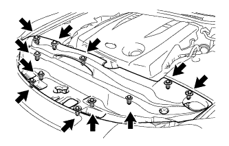
| 8. INSTALL V-BANK COVER SUB-ASSEMBLY |
Engage the 2 clips on the front of the cover, and then engage the clip on the rear to install the V-bank cover.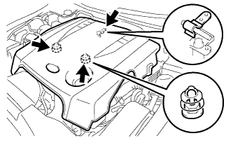
- NOTICE:
- Be sure to engage the clips securely.
- Do not apply excessive force or do not hit the cover to engage the clips. This may cause the cover to break.
- Be sure to engage the clips securely.
| 9. CONNECT BATTERY NEGATIVE TERMINAL |
- Torque:
- 5.4 N*m{ 55 kgf*cm , 48 in.*lbf }
| 10. PERFORM INITIALIZATION |
Perform initialization (Click here).
- NOTICE:
- Certain systems need to be initialized after disconnecting and reconnecting the cable from the negative (-) battery terminal.