DISASSEMBLY
Removal / installation
| 1. REMOVE OIL FILLER CAP SUB-ASSEMBLY |

Remove the oil filler cap and gasket.
| 2. REMOVE RADIATOR CAP SUB-ASSEMBLY |
Remove the radiator cap.
| 3. REMOVE SPARK PLUG |
| 4. REMOVE OIL PAN DRAIN PLUG |
Remove the drain plug and gasket.
| 5. REMOVE VENTILATION VALVE SUB-ASSEMBLY |
Remove the ventilation valve.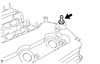

| 6. REMOVE CAMSHAFT POSITION SENSOR |
Remove the 4 bolts and 4 sensors.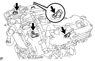
| 7. REMOVE CAMSHAFT TIMING OIL CONTROL VALVE ASSEMBLY |
Remove the 4 bolts and 4 oil control valves.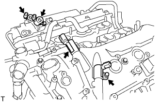
| 8. REMOVE CRANKSHAFT POSITION SENSOR |
Remove the bolt and sensor.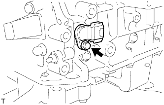
| 9. REMOVE NO. 1 OIL PIPE |
Remove the oil check valve bolt, oil pipe union and oil pipe.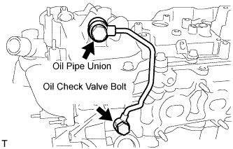
Remove the oil control valve filter LH and gaskets.
| 10. REMOVE NO. 2 OIL PIPE |
Remove the oil check valve bolt, oil pipe union and oil pipe.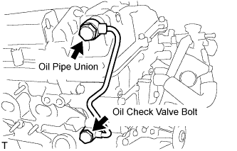
Remove the oil control valve filter RH and gaskets.
| 11. REMOVE CYLINDER BLOCK WATER DRAIN COCK SUB-ASSEMBLY |
Remove the water drain cocks from the cylinder block.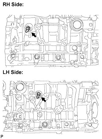
Remove the water drain cock plugs from the water drain cocks.
| 12. REMOVE OIL FILTER ELEMENT |
Using SST, remove the oil filter cap.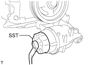
- SST
- 09228-06501
- HINT:
- Place a container for oil to be drained before removing the cap.
Remove the oil filter element and O-ring from the oil filter cap.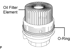
- NOTICE:
- Do not use any tools when removing the O-ring to prevent the O-ring groove from being damaged.
| 13. REMOVE CRANKSHAFT PULLEY |
Using SST, loosen the crankshaft pulley bolt.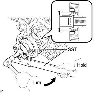
- SST
- 09213-70011
(09213-70020)
09330-00021
Using SST, remove the crankshaft pulley bolt and crankshaft pulley.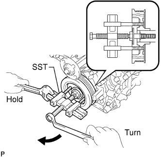
- SST
- 09950-50013
(09951-05010, 09952-05010, 09953-05020, 09954-05021)
| 14. REMOVE WATER INLET ASSEMBLY |
Separate the 3 water by-pass hoses.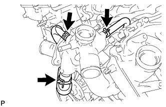
Remove the 4 bolts, nut and water inlet.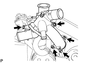
Remove the 2 O-rings.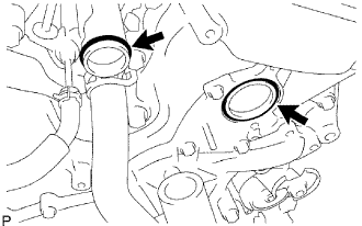
Remove the 3 water by-pass hoses.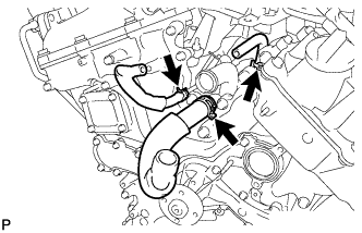
| 15. REMOVE WATER INLET WITH THERMOSTAT SUB-ASSEMBLY |
Remove the 3 nuts and water inlet with thermostat.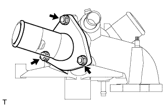
Remove the gasket from the water inlet.
| 16. REMOVE REAR WATER BY-PASS JOINT |
Remove the 2 bolts, 4 nuts and water by-pass joint.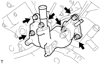
Remove the 2 gaskets and O-ring.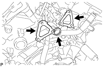
| 17. REMOVE CYLINDER HEAD COVER SUB-ASSEMBLY (for Bank 1) |
Remove the 14 bolts, head cover and gasket.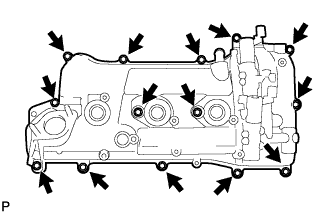
Remove the 3 gaskets.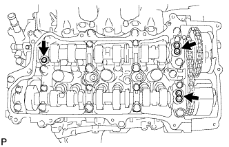
| 18. REMOVE CYLINDER HEAD COVER SUB-ASSEMBLY (for Bank 2) |
Remove the 12 bolts, head cover and gasket.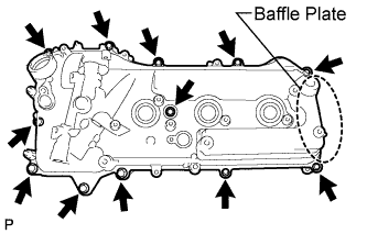
- NOTICE:
- The baffle plate is located on the back of the portion shown in the illustration. Do not damage the baffle plate when removing the head cover.
Remove the 3 gaskets.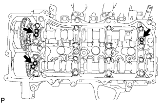
| 19. REMOVE SPARK PLUG TUBE GASKET |
Pry up the claws of the ventilation baffle plate.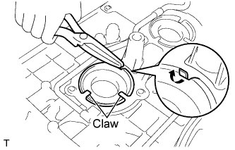
- NOTICE:
- Do not deform the claws of the baffle plate more than necessary.
Remove the 6 gaskets from the cylinder head covers.
- NOTICE:
- As much as possible prevent the plug tube gaskets from being deformed. The removed gaskets will be used when reinstalling the gaskets.
- Do not damage the connection of the cylinder head cover.
- As much as possible prevent the plug tube gaskets from being deformed. The removed gaskets will be used when reinstalling the gaskets.
| 20. REMOVE NO. 2 OIL PAN SUB-ASSEMBLY |
Remove the 15 bolts and 2 nuts.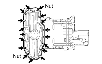
Insert the blade of SST between the oil pans. Cut through the applied sealer and remove the No. 2 oil pan sub-assembly.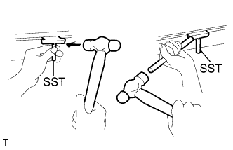
- SST
- 09032-00100
- NOTICE:
- Be careful not to damage the contact surfaces of the oil pans.
| 21. REMOVE OIL PAN SUB-ASSEMBLY |
Remove the 16 bolts and 2 nuts.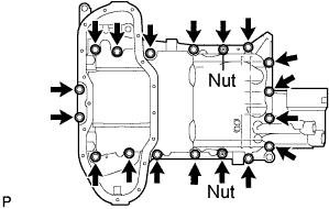
- HINT:
- Be sure to clean the bolts and stud bolts and check the threads for cracks or other damage.
Remove the oil pan by prying between the oil pan and cylinder block with a screwdriver.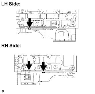
- NOTICE:
- Be careful not to damage the contact surfaces of the cylinder block and oil pan.
- HINT:
- Tape the screwdriver tip before use.
Remove the 2 O-rings.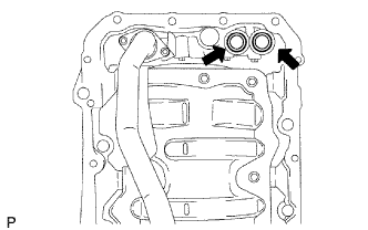
| 22. REMOVE OIL STRAINER SUB-ASSEMBLY |
Remove the 3 nuts, oil strainer and gasket.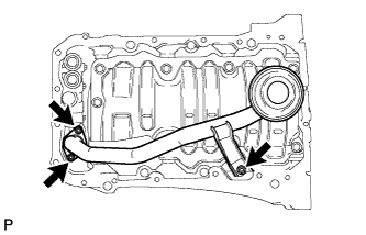
Remove the 8 bolts and baffle plate.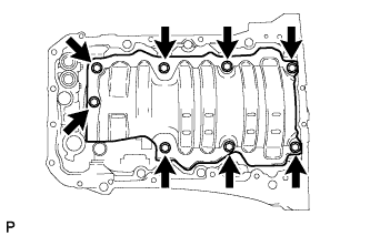
| 23. REMOVE ENGINE REAR OIL SEAL RETAINER |
Remove the 6 bolts.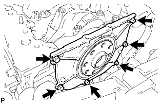
Using a screwdriver, pry out the oil seal retainer.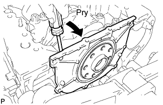
- NOTICE:
- Be careful not to damage the engine rear oil seal retainer.
- HINT:
- Tape the screwdriver tip before use.
| 24. REMOVE ENGINE REAR OIL SEAL |
Place the oil seal retainer on wooden blocks.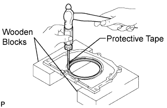
- NOTICE:
- Be careful not to damage the engine rear oil seal retainer.
Using a screwdriver and a hammer, tap out the oil seal.
- HINT:
- Tape the screwdriver tip before use.
| 25. REMOVE WATER PUMP ASSEMBLY |
Remove the 16 bolts, water pump and gasket.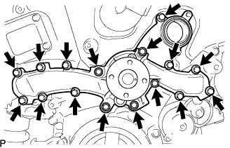
| 26. REMOVE TIMING CHAIN COVER SUB-ASSEMBLY |
Remove the 16 bolts and 2 nuts as shown in the illustration.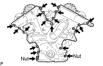
Remove the timing chain cover by prying between the timing chain cover and cylinder head or cylinder block with a screwdriver.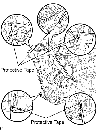
- NOTICE:
- Be careful not to damage the contact surfaces of the cylinder head, cylinder block and chain cover.
- HINT:
- Tape the screwdriver tip before use.
Remove the 4 bolts, chain cover plate and gasket.
Remove the gasket.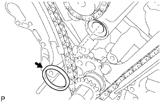
| 27. REMOVE TIMING CHAIN CASE OIL SEAL |
Using a screwdriver, pry out the oil seal.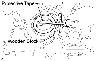
- HINT:
- Tape the screwdriver tip before use.
| 28. SET NO. 1 CYLINDER TO TDC / COMPRESSION |
Temporarily tighten the pulley set bolt.
Set the timing mark on the crank angle sensor plate to the RH block bore center line (TDC / compression).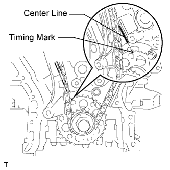
Check that the timing marks of the camshaft timing gears are aligned with the timing marks of the bearing cap as shown in the illustration.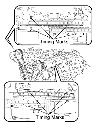
If not, turn the crankshaft 1 revolution (360°) and align the timing marks as above.
| 29. REMOVE NO. 1 CHAIN TENSIONER ASSEMBLY |
Move the stopper plate upward to release the lock, and push the plunger deep into the tensioner.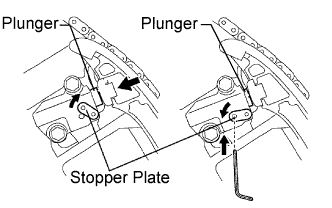
Move the stopper plate downward to set the lock, and insert a hexagon wrench into the stopper plate's hole.
Remove the 2 bolts and chain tensioner.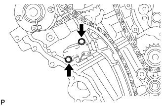
| 30. REMOVE CHAIN TENSIONER SLIPPER |
Remove the chain tensioner slipper.
| 31. REMOVE CHAIN SUB-ASSEMBLY |
Turn the crankshaft counterclockwise 10° to loosen the chain of the crankshaft timing sprocket.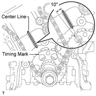
Remove the pulley set bolt.
Remove the chain from the crankshaft timing sprocket and place it on the crankshaft.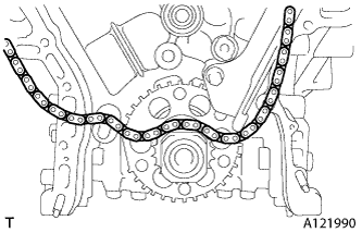
Turn the camshaft timing gear assembly on the RH bank clockwise (approximately 60°) and set it as shown in the illustration. Be sure to loosen the chain between the banks.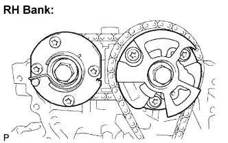
Remove the chain.
| 32. REMOVE IDLE SPROCKET ASSEMBLY |
Using a 10 mm hexagon wrench, remove the No. 2 idle gear shaft, sprocket and No. 1 idle gear shaft.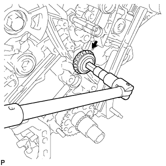
| 33. REMOVE NO. 1 CHAIN VIBRATION DAMPER |
Remove the 2 bolts and vibration damper.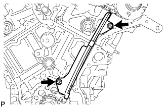
| 34. REMOVE NO. 2 CHAIN VIBRATION DAMPER |
Remove the 2 vibration dampers.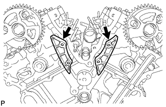
| 35. REMOVE CRANKSHAFT TIMING SPROCKET |
Remove the crankshaft timing sprocket from the crankshaft.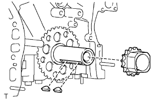
Remove the 2 pulley set keys from the crankshaft.
| 36. REMOVE CAMSHAFT TIMING GEARS AND NO. 2 CHAIN (for Bank 1) |
While raising the No. 2 chain tensioner, insert a pin of φ 1.0 mm (0.039 in.) into the hole to fix the No. 2 chain tensioner.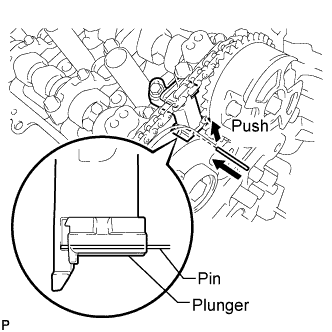
Hold the hexagonal portion of the camshaft with a wrench, and remove the 2 bolts and 2 camshaft timing gear assemblies.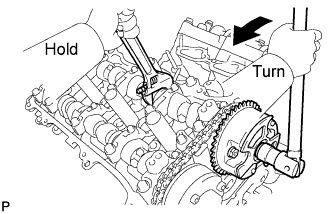
- NOTICE:
- Be careful not to damage the cylinder head with the wrench.
- Do not disassemble the camshaft timing gear assemblies.
- Be careful not to damage the cylinder head with the wrench.
Remove the No. 2 chain.
| 37. REMOVE NO. 2 CHAIN TENSIONER ASSEMBLY |
Remove the bolt and No. 2 chain tensioner.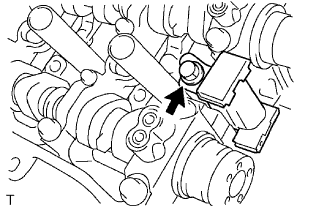
| 38. REMOVE CAMSHAFT BEARING CAP (for Bank 1) |
Check that the camshafts are positioned as shown in the illustration.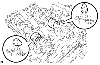
Uniformly loosen and remove the 9 bearing cap bolts in the sequence shown in the illustration.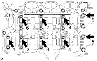
Uniformly loosen and remove the 14 bearing cap bolts in the sequence shown in the illustration.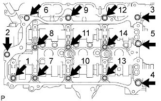
- NOTICE:
- Uniformly loosen the bolts while keeping the camshaft level.
Remove the 6 bearing caps.
| 39. REMOVE CAMSHAFT |
Remove the camshaft.
| 40. REMOVE NO. 2 CAMSHAFT |
Remove the No. 2 camshaft.
| 41. REMOVE CAMSHAFT HOUSING SUB-ASSEMBLY RH |
Remove the camshaft housing sub-assembly RH by prying between the cylinder head and camshaft housing sub-assembly RH with a screwdriver.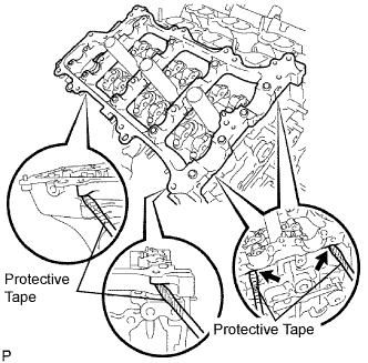
- NOTICE:
- Be careful not to damage the contact surfaces of the cylinder head and camshaft housing.
- HINT:
- Tape the screwdriver tip before use.
| 42. REMOVE CAMSHAFT TIMING GEARS AND NO. 2 CHAIN (for Bank 2) |
While pushing down the No. 3 chain tensioner, insert a pin of φ 1.0 mm (0.039 in.) into the hole to fix the No. 3 chain tensioner.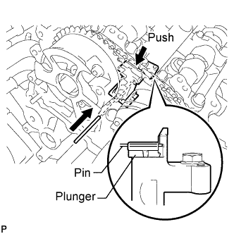
Hold the hexagonal portion of the camshaft with a wrench, and remove the 2 bolts and 2 camshaft timing gear assemblies.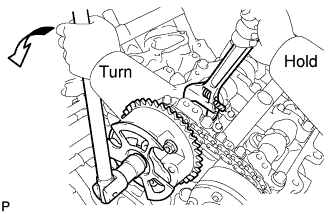
- NOTICE:
- Be careful not to damage the cylinder head with the wrench.
- Do not disassemble the camshaft timing gear assemblies.
- Be careful not to damage the cylinder head with the wrench.
Remove the No. 2 chain.
| 43. REMOVE NO. 3 CHAIN TENSIONER ASSEMBLY |
Remove the bolt and No. 3 chain tensioner.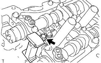
| 44. REMOVE CAMSHAFT BEARING CAP (for Bank 2) |
Check that the camshafts are positioned as shown in the illustration.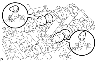
Uniformly loosen and remove the 8 bearing cap bolts in the sequence shown in the illustration.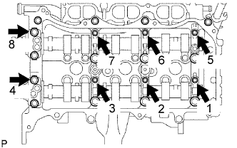
Uniformly loosen and remove the 13 bearing cap bolts in the sequence shown in the illustration.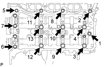
- NOTICE:
- Uniformly loosen the bolts while keeping the camshaft level.
Remove the 5 bearing caps.
| 45. REMOVE NO. 3 CAMSHAFT |
Remove the No. 3 camshaft.
| 46. REMOVE NO. 4 CAMSHAFT |
Remove the No. 4 camshaft.
| 47. REMOVE CAMSHAFT HOUSING SUB-ASSEMBLY LH |
Remove the camshaft housing by prying between the cylinder head and camshaft housing with a screwdriver.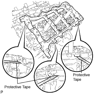
- NOTICE:
- Be careful not to damage the contact surfaces of the cylinder head and camshaft housing.
- HINT:
- Tape the screwdriver tip before use.
| 48. REMOVE NO. 1 VALVE ROCKER ARM SUB-ASSEMBLY |
Remove the 24 valve rocker arms.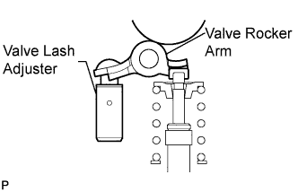
- HINT:
- Arrange the removed parts in the correct order.
| 49. REMOVE VALVE LASH ADJUSTER ASSEMBLY |
Remove the 24 valve lash adjusters from the cylinder head.
- HINT:
- Arrange the removed parts in the correct order.
| 50. REMOVE CYLINDER HEAD SUB-ASSEMBLY RH |
Using a 10 mm bi-hexagon wrench, uniformly loosen the 8 bolts in the sequence shown in the illustration. Remove the 8 cylinder head bolts and plate washers.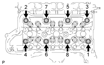
- NOTICE:
- Be careful not to drop washers into the cylinder head.
- Cylinder head warpage or cracking could result from removing bolts in an incorrect order.
- Be careful not to drop washers into the cylinder head.
- HINT:
- Be sure to keep separate the removed parts for each installation position.
Remove the cylinder head and gasket.
| 51. REMOVE CYLINDER HEAD SUB-ASSEMBLY LH |
Uniformly loosen and remove the bolts in the sequence shown in the illustration.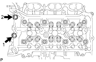
Using a 10 mm bi-hexagon wrench, uniformly loosen the 8 bolts in the sequence shown in the illustration. Remove the 8 cylinder head bolts and plate washers.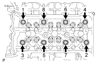
- NOTICE:
- Be careful not to drop washers into the cylinder head.
- Cylinder head warpage or cracking could result from removing bolts in an incorrect order.
- Be careful not to drop washers into the cylinder head.
- HINT:
- Be sure to keep separate the removed parts for each installation position.
Remove the cylinder head and gasket.
| 52. REMOVE CYLINDER BLOCK WATER JACKET SPACER RH |
Using needle-nose pliers, remove the cylinder block water jacket spacer RH.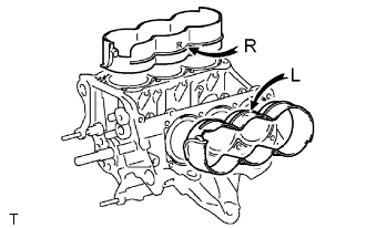
- NOTICE:
- Be sure to remove the water jacket spacer if turning the cylinder block.
| 53. REMOVE CYLINDER BLOCK WATER JACKET SPACER LH |
Using needle-nose pliers, remove the cylinder block water jacket spacer LH.
- NOTICE:
- Be sure to remove the water jacket spacer if turning the cylinder block.
| 54. REMOVE KNOCK SENSOR |
Disconnect the knock sensor wire.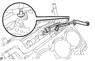
Disconnect the 2 knock sensor connectors.
Remove the 2 bolts and knock sensors.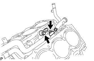
| 55. REMOVE WATER OUTLET PIPE SUB-ASSEMBLY |
Remove the 2 bolts and water outlet pipe.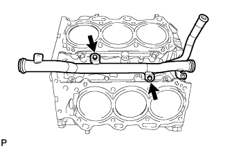
| 56. REMOVE VALVE STEM CAP |
Remove the valve stem caps from the cylinder heads.
- HINT:
- Arrange the removed parts in the correct order.
| 57. REMOVE INTAKE VALVE |
Using SST, compress the compression spring and remove the valve spring retainer locks.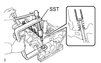
- SST
- 09202-70020
(09202-00010)
Remove the retainer, compression spring and valve.
- HINT:
- Arrange the removed parts in the correct order.
| 58. REMOVE EXHAUST VALVE |
Using SST, compress the compression spring and remove the valve spring retainer locks.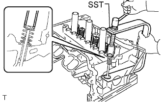
- SST
- 09202-70020
(09202-00010)
Remove the retainer, compression spring and valve.
- HINT:
- Arrange the removed parts in the correct order.
| 59. REMOVE VALVE STEM OIL SEAL |
Using needle-nose pliers, remove the oil seals.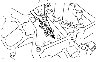
| 60. REMOVE VALVE SPRING SEAT |
Using compressed air and a magnetic finger, remove the valve spring seats by blowing air onto them.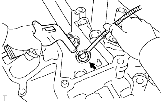
| 61. REMOVE NO. 1 STRAIGHT SCREW PLUG |
Using a 10 mm hexagon wrench, remove the 4 screw plugs and 4 gaskets.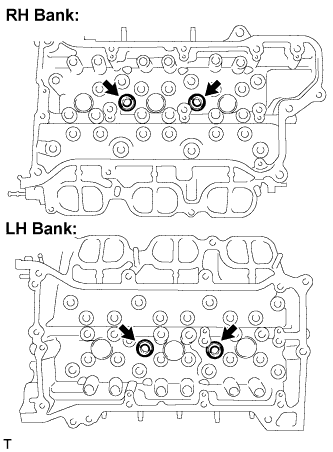
- NOTICE:
- If water leaks from the straight screw plug or the plug corrodes, replace it.
| 62. REMOVE NO. 2 STRAIGHT SCREW PLUG |
Using a 14 mm hexagon wrench, remove the screw plugs and gaskets.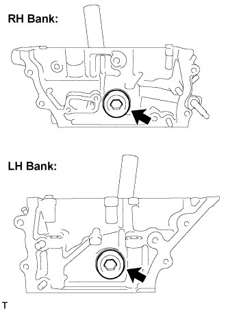
- NOTICE:
- If water leaks from the straight screw plug or the plug corrodes, replace it.
| 63. REMOVE UNION |
Remove the unions from the cylinder heads.
| 64. REMOVE RING PIN |
- NOTICE:
- It is not necessary to remove the ring pin unless it is being replaced.
| 65. REMOVE STUD BOLT |
- NOTICE:
- If the stud bolt is deformed or the threads are damaged, replace it.
| 66. REMOVE INTAKE VALVE GUIDE BUSH |
Heat the cylinder head to 80 to 100°C (176 to 212°F).
Place the cylinder head on wooden blocks.
Using SST and a hammer, tap out the guide bushes.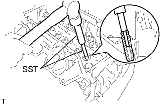
- SST
- 09201-10000
(09201-01050)
09950-70010 (09951-07100)
| 67. REMOVE EXHAUST VALVE GUIDE BUSH |
Heat the cylinder head to 80 to 100°C (176 to 212°F).
Place the cylinder head on wooden blocks.
Using SST and a hammer, tap out the guide bushes.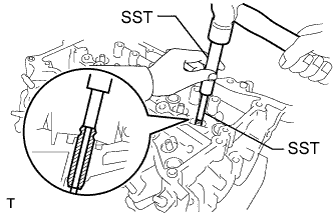
- SST
- 09201-10000
(09201-01050)
09950-70010 (09951-07100)
| 68. REMOVE PISTON SUB-ASSEMBLY WITH CONNECTING ROD |
Check that the matchmarks on the connecting rod and cap are aligned.
- HINT:
- The matchmarks on the connecting rods and caps are for ensuring the correct reassembly.
Remove the 2 connecting rod cap bolts.
Using the 2 removed connecting rod caps bolts, remove the connecting rod cap and lower bearing by wiggling the connecting rod cap right and left.
- HINT:
- Keep the lower bearing inserted to the connecting rod cap.
Using a ridge reamer, remove all the carbon from the top of the cylinder.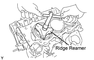
Push the piston, connecting rod assembly and upper bearing through the top of the cylinder block.
- HINT:
- Keep the bearing, connecting rod and cap together.
- Arrange the piston and connecting rod assemblies in the correct order.
- Keep the bearing, connecting rod and cap together.
| 69. REMOVE CONNECTING ROD BEARING |
- NOTICE:
- Arrange the removed parts in the correct order.
| 70. REMOVE CRANKSHAFT |
Uniformly loosen and remove the 8 main bearing cap bolts and seal washers in the several steps and in the sequence shown in the illustration.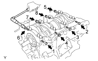
Uniformly loosen the 16 bearing cap bolts, in several steps, in the sequence shown in the illustration.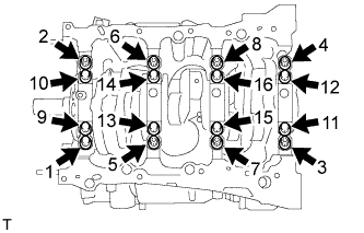
Using a screwdriver, pry out the main bearing caps. Remove the 4 main bearing caps and lower bearings.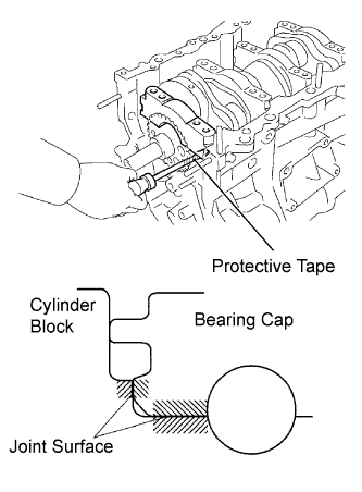
- NOTICE:
- Push up on the cap little by little, from the right and left side alternately until the cap can be removed.
- Be careful not to damage the joint surface of the cylinder block and the main bearing cap.
- Push up on the cap little by little, from the right and left side alternately until the cap can be removed.
Remove the crankshaft.
| 71. REMOVE CRANKSHAFT BEARING |
- HINT:
- Arrange the removed parts in the correct order.
| 72. REMOVE CRANKSHAFT THRUST WASHER SET |
Remove the upper bearings and upper thrust washers from the cylinder block.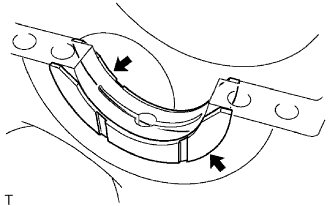
| 73. REMOVE PISTON RING SET |
Using a piston ring expander, remove the 2 compression rings.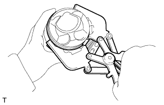
Using a piston ring expander, remove the oil ring rail.
Remove the oil ring expander by hand.
- HINT:
- Arrange the removed parts in the correct order.
| 74. REMOVE PISTON SUB-ASSEMBLY WITH PIN |
Disconnect the connecting rod from the piston.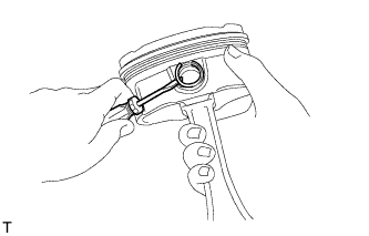
Using a screwdriver, pry off the snap rings from the piston.
Gradually heat the piston to approximately 80°C (176°F).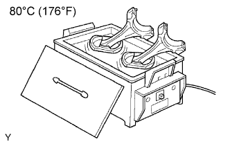
Using a brass bar and plastic hammer, lightly tap out the piston pin and remove the connecting rod.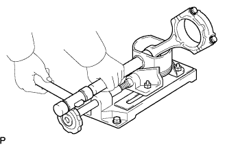
- HINT:
- The piston and pin are a matched set.
- Arrange the pistons, pins, rings, connecting rods and bearings in the correct order.
- The piston and pin are a matched set.
Using a gasket scraper, remove the carbon from the piston top.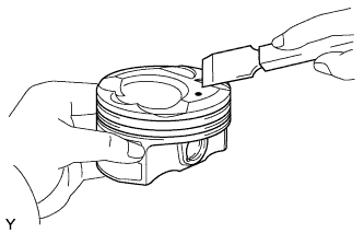
Using a groove cleaning tool or broken ring, clean the piston ring grooves.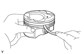
Using solvent and a brush, thoroughly clean the piston.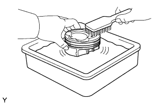
- NOTICE:
- Do not use a wire brush.
| 75. REMOVE NO. 1 OIL NOZZLE SUB-ASSEMBLY |
Using a 5 mm hexagon wrench, remove the bolts and oil nozzles.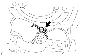
Check the 3 oil nozzles for damage or clogging.
| 76. REMOVE CONNECTING ROD SMALL END BUSH |
Using SST and press, press out the bush.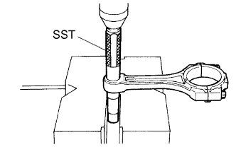
- SST
- 09222-30010