REASSEMBLY
Removal / installation
| 1. INSTALL STRAIGHT PIN |

Using a plastic hammer, tap in new straight pins to the cylinder block.
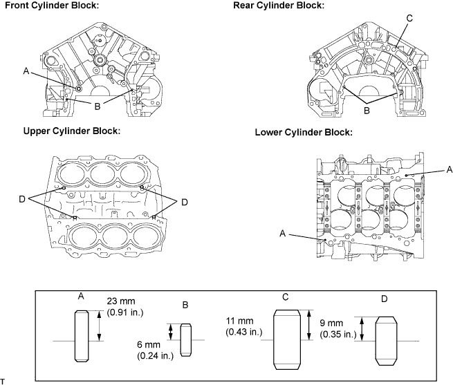

- Standard protrusion:
Item
Protrusion
Pin A
6 mm (0.236 in.)
Pin B
23 mm (0.906 in.)
Pin C
11 mm (0.433 in.)
Pin D
9 mm (0.354 in.)
| 2. INSTALL STUD BOLT |
Using an E8 "torx" socket, install the stud bolts.
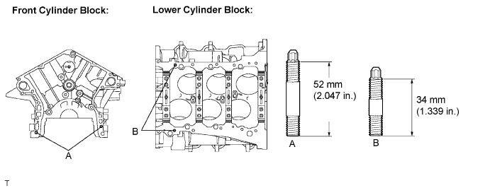
- Torque:
- 10 N*m{ 102 kgf*cm , 7 ft.*lbf }
| 3. INSTALL TIGHT PLUG |
- NOTICE:
- If water leaks from the tight plug or the plug corrodes, replace it.
Apply adhesive around the tight plugs.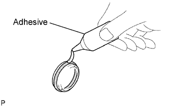
- Adhesive:
- Part No. 08833-00070, THREE BOND 1324 or equivalent.
Using SST and a hammer, tap in new tight plugs as shown in the illustration.
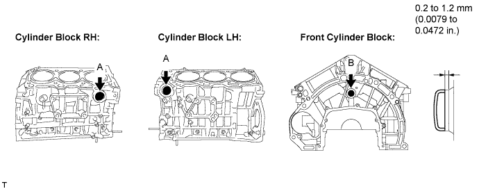
Using SST, tap in the 2 tight plugs A.
- SST
- 09950-60010
(09951-00340)
09950-70010 (09951-07100)
Using SST, tap in the tight plug B.
- SST
- 09950-60010
(09951-00200)
09950-70010 (09951-07100)
| 4. INSTALL NO. 1 OIL NOZZLE SUB-ASSEMBLY |
Using a 5 mm hexagon wrench, install the oil nozzles.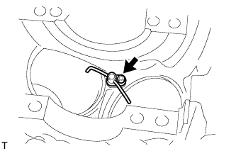
- Torque:
- 9.0 N*m{ 92 kgf*cm , 80 in.*lbf }
| 5. INSTALL CONNECTING ROD SMALL END BUSH |
Align the oil holes of a new bush and the connecting rod.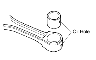
Using SST and a press, press in the bush.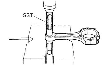
- SST
- 09222-30010
Using a pin hole grinder, hone the bush to obtain the specified clearance between the bush and piston pin.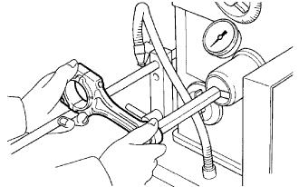
- Standard oil clearance:
- -0.002 to 0.004 mm (-0.00007 to 0.0001 in.)
Check that the piston pin fits at normal room temperature.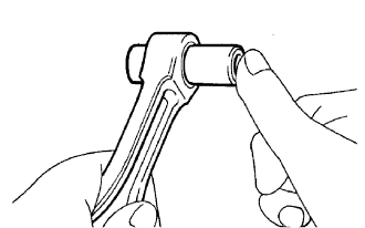
Coat the piston pin with engine oil, and push it into the connecting rod with your thumb.
| 6. INSTALL PISTON SUB-ASSEMBLY WITH PIN |
Using a screwdriver, install a new snap ring at one end of the piston pin hole.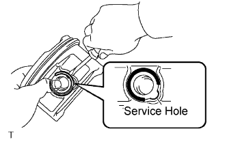
- HINT:
- Be sure that the end gap of the snap ring is not aligned with the pin hole cutout portion of the piston.
Gradually heat the piston to approximately 80°C (176°F).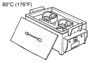
Coat the piston pin with engine oil.
Align the front marks of the piston and connecting rod, and push in the piston pin with your thumb.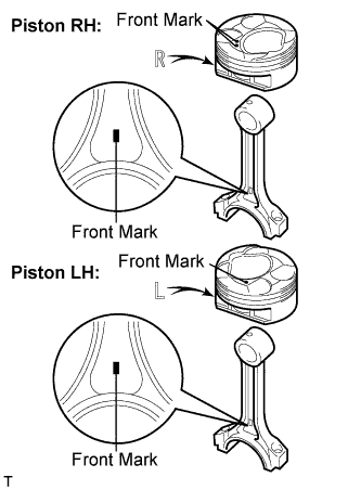
- Front Mark:
Item
Front Mark
Piston LH
1
Piston RH
2
- HINT:
- The piston and pin are a matched set.
Check the fitting condition between the piston and piston pin by trying to move the piston back and forth on the piston pin.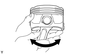
Using a screwdriver, install a new snap ring at the other end of the piston pin hole.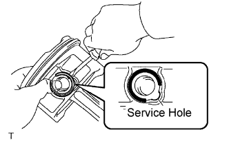
- HINT:
- Be sure that the end gap of the snap ring is not aligned with the pin hole cutout portion of the piston.
| 7. INSTALL PISTON RING SET |
Install the oil ring expander by hand.
Using a piston ring expander, install the oil ring rail and 2 compression rings as shown in the illustration.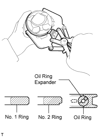
Position the piston rings so that the ring ends are as shown in the illustration.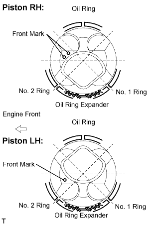
- NOTICE:
- Do not align the ring ends.
| 8. INSTALL CRANKSHAFT BEARING |
Clean the main journal and the both surfaces of the bearing.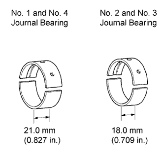
- NOTICE:
- Main bearings come in widths between 18.0 mm (0.709 in.) and 21.0 mm (0.827 in.). Install the 21.0 mm (0.827 in.) bearings in the No. 1 and No. 4 cylinder block journal positions with the main bearing cap. Install the 18.0 mm (0.709 in.) bearings in the No. 2 and No. 3 positions.
Install the upper bearing.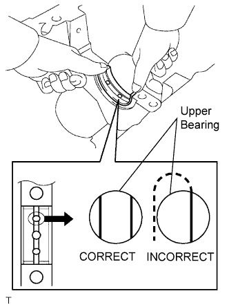
Install the upper bearings to the cylinder block as shown in the illustration.
- NOTICE:
- Do not apply engine oil to the bearings and the contact surfaces.
- Both sides of the oil groove in the cylinder block should be visible through the oil feed holes in the bearing. The amount visible on each side of the holes should be equal.
- Do not apply engine oil to the bearings and the contact surfaces.
Install the lower bearing.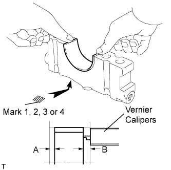
Install the lower bearings to the bearing caps.
Using vernier calipers, measure the distance between the bearing cap's edge and the lower bearing's edge.
- Dimension (A - B):
- 0.7 mm (0.0276 in.) or less
- NOTICE:
- Do not apply engine oil to the bearings and the contact surfaces.
| 9. INSTALL CRANKSHAFT THRUST WASHER SET |
Apply engine oil to the crankshaft thrust washer.
Install the 2 thrust washers under the No. 2 journal position of the cylinder block with the oil grooves facing outward.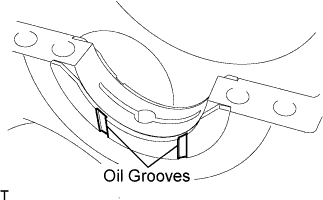
| 10. INSTALL CRANKSHAFT |
Apply engine oil to the upper bearing, then place the crankshaft on the cylinder block.
Confirm the projection and numbers of the main bearing caps and install the bearing caps on the cylinder block.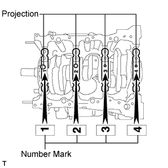
- HINT:
- A number is marked on each main bearing cap to indicate the installation position.
Apply a light coat of engine oil to the threads and under the heads of the bearing cap bolts.
Temporarily install the 8 main bearing cap bolts to the inside positions.
Insert the main bearing cap with your hand until the clearance between the main bearing cap and the cylinder block is less than 6 mm (0.23 in.) by marking the 2 internal bearing cap bolts as a guide.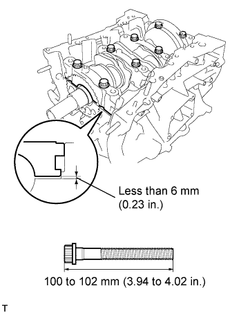
- Bolt length:
- 100 to 102 mm (3.94 to 4.02 in.)
Using a plastic hammer, lightly tap the bearing cap to ensure a proper fit.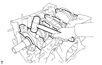
Apply a light coat of engine oil to the threads and under the heads of the 8 main bearing cap bolts.
Install the 8 main bearing cap bolts to the outside positions.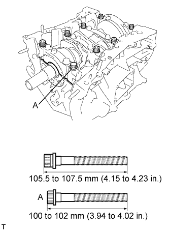
- Bolt length:
Item
Length
Bolt A
100 to 102 mm (3.94 to 4.02 in.)
Except bolt A
105.5 to 107.5 mm (4.15 to 4.23 in.)
Install the crankshaft bearing cap bolts.
- HINT:
- The main bearing cap bolts are tightened in 2 progressive steps.
Step 1
Install and uniformly tighten the 16 main bearing cap bolts in the sequence shown in the illustration.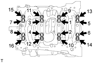
- Torque:
- 61 N*m{ 622 kgf*cm , 45 ft.*lbf }
Step 2
Mark the front of the bearing cap bolts with paint.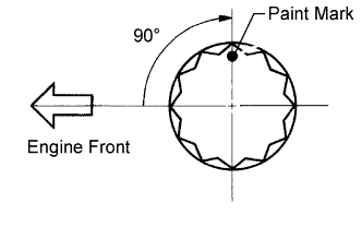
Retighten the bearing cap bolts by 90° in the order above.
Check that the painted mark is now at a 90° angle to the front.
Install 8 new seal washers and uniformly tighten the 8 main bearing cap bolts in several steps and in the sequence shown in the illustration.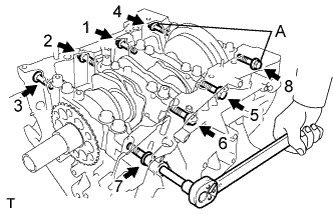
- Torque:
- 26 N*m{ 265 kgf*cm , 19 ft.*lbf }
- Bolt length:
Item
Length
Bolt A
45 mm (1.77 in.)
Except bolt A
30 mm (1.18 in.)
Check that the crankshaft turns smoothly.
Check the crankshaft thrust clearance (Click here).
| 11. INSTALL CONNECTING ROD BEARING |
Install the connecting rod bearing to the connecting rod and bearing cap.
Using vernier calipers, measure the distance between the connecting rod's and bearing cap's edges and the connecting rod bearing's edge.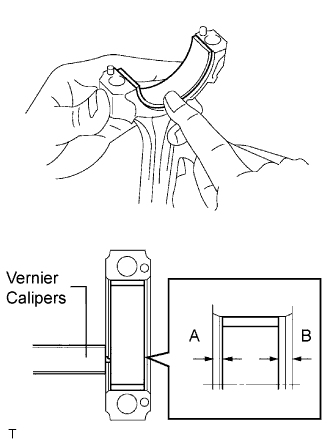
- Dimension (A - B):
- 0.7 mm (0.0276 in.) or less
- NOTICE:
- Do not apply engine oil to the bearings and the contact surfaces.
| 12. INSTALL PISTON SUB-ASSEMBLY WITH CONNECTING ROD |
Apply engine oil to the cylinder walls, the pistons, and the surfaces of the connecting rod bearings.
Position the piston rings so that the ring ends are as shown in the illustration.
- NOTICE:
- Do not align the ring ends.
Using a piston ring compressor, push the correctly numbered piston and connecting rod assembly into the cylinder with the front mark of the piston facing forward.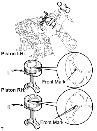
- NOTICE:
- Match the numbered connecting rod cap with the connecting rod.
- Front Mark:
Item
Front Mark
Piston LH
1
Piston RH
2
Check that the front mark of the connecting rod cap is facing forward.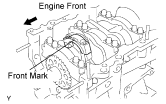
Apply a light coat of engine oil to the threads and under the heads of the connecting rod cap bolts.
Install the connecting cap bolts.
- HINT:
- The connecting cap bolts are tightened in 2 progressive steps.
Step 1
Install and alternately tighten the bolts of the connecting rod cap in several steps.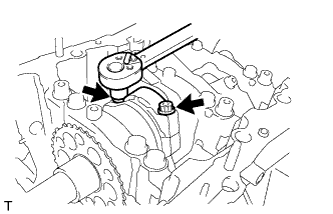
- Torque:
- 25 N*m{ 255 kgf*cm , 18 ft.*lbf }
Step 2
Mark the front side of each connecting cap bolt with paint.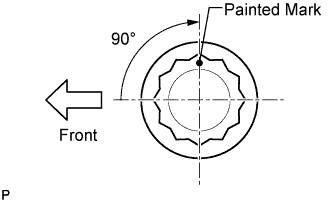
Retighten the cap bolts by 90° as shown in the illustration.
Check the painted mark is now at a 90° angle to the front.
Check that the crankshaft turns smoothly.
Check the connecting rod thrust clearance (Click here).
| 13. INSTALL INTAKE VALVE GUIDE BUSH |
Using a caliper gauge, measure the bush bore diameter of the cylinder head.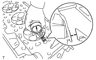
- Cylinder bore diameter:
- 10.285 to 10.306 mm (0.4049 to 0.4057 in.)
- Select a new guide bush (STD or O/S 0.05):
Bush size
Bush bore diameter
Use STD
10.285 to 10.306 mm (0.4049 to 0.4057 in.)
Use O/S 0.05
10.335 to 10.356 mm (0.4069 to 0.4077 in.)
If the bush bore diameter of the cylinder head is greater than 10.356 mm (0.4077 in.), replace the cylinder head.
Heat the cylinder head to 80 to 100°C (176 to 212°F).
Place the cylinder head on wooden blocks.
Using SST, tap in new valve guide bushes to the specified protrusion height.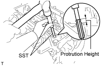
- SST
- 09201-10000
(09201-01050)
09950-70010 (09951-07100)
- Protrusion height:
- 10.20 to 10.24 mm (0.4016 to 0.4031 in.)
Using a sharp 5.5 mm reamer, ream the valve guide bushings to obtain the specified clearance.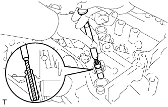
- Standard oil clearance:
- 0.025 to 0.060 mm (0.0010 to 0.0023 in.)
| 14. INSTALL EXHAUST VALVE GUIDE BUSH |
Using a caliper gauge, measure the bush bore diameter of the cylinder head.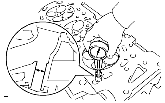
- Cylinder bore diameter:
- 10.285 to 10.306 mm (0.4049 to 0.4057 in.)
- Select a new guide bush (STD or O/S 0.05):
Bush size
Bush bore diameter
Use STD
10.285 to 10.306 mm (0.4049 to 0.4057 in.)
Use O/S 0.05
10.335 to 10.356 mm (0.4069 to 0.4077 in.)
If the bush bore diameter of the cylinder head is greater than 10.356 mm (0.4077 in.), replace the cylinder head.
Heat the cylinder head to 80 to 100°C (176 to 212°F).
Place the cylinder head on wooden blocks.
Using SST, tap in new valve guide bushes to the specified protrusion height.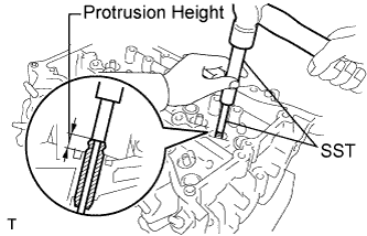
- SST
- 09201-10000
(09201-01050)
09950-70010 (09951-07100)
- Protrusion height:
- 9.30 to 9.34 mm (0.3661 to 0.3677 in.)
Using a sharp 5.5 mm reamer, ream the valve guide bushings to obtain the specified clearance.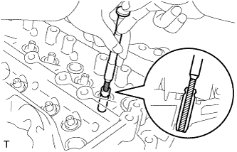
- Standard oil clearance:
- 0.030 to 0.065 mm (0.0012 to 0.0026 in.)
| 15. INSTALL RING PIN |
Using a plastic hammer, tap in new ring pins to the specified protrusion height.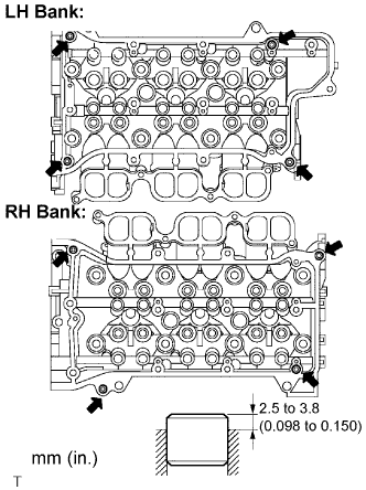
- Specified protrusion height:
- 2.5 to 3.8 mm (0.098 to 0.150 in.)
| 16. INSTALL NO. 1 STRAIGHT SCREW PLUG |
Using a 10 mm hexagon wrench, install 4 new gaskets and the straight screw plugs.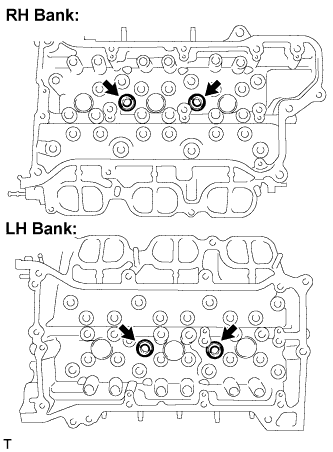
- Torque:
- 44 N*m{ 449 kgf*cm , 32 ft.*lbf }
| 17. INSTALL NO. 2 STRAIGHT SCREW PLUG |
Using a 14 mm hexagon wrench, install 2 new gaskets and the 2 straight screw plugs.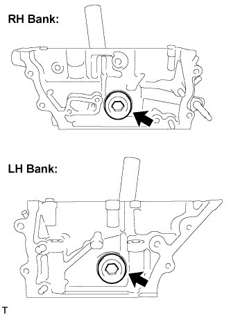
- Torque:
- 80 N*m{ 816 kgf*cm , 59 ft.*lbf }
| 18. INSTALL STUD BOLT |
- NOTICE:
- If the stud bolt is deformed or the threads are damaged, replace it.
Using E6 and E8 "torx" sockets, install the stud bolts.
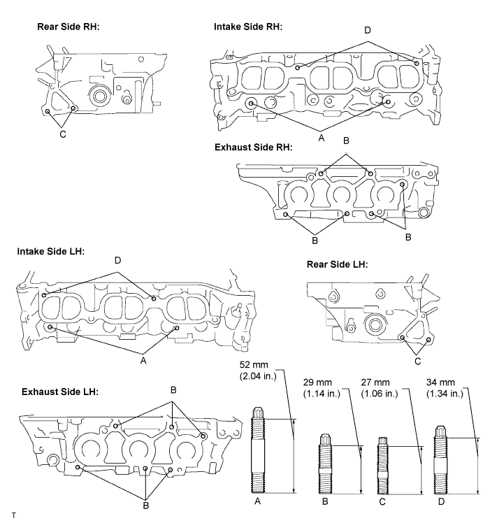
- Torque:
- 10 N*m{ 102 kgf*cm , 7 ft.*lbf } for bolts A, B and D
- 4.0 N*m{ 41 kgf*cm , 35 in.*lbf } for bolt C
| 19. INSTALL UNION |
Apply adhesive to the union of the cylinder head.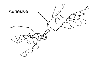
- Adhesive:
- Part No. 08833-00070, THREE BOND 1324 or equivalent.
Using SST, install the union to the cylinder head as shown in the illustration.
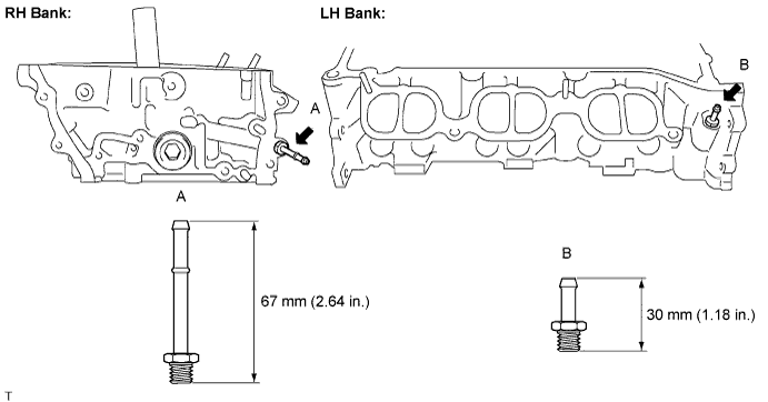
- SST
- 09023-38201
- Torque:
- 15 N*m{ 153 kgf*cm , 11 ft.*lbf }
| 20. INSTALL STRAIGHT PIN |
Using a plastic hammer, tap in new straight pins as shown in the illustration.
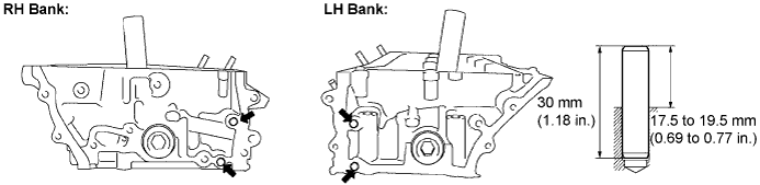
- Protrusion height:
- 17.5 to 19.5 mm (0.689 to 0.768 in.)
| 21. INSTALL VALVE SPRING SEAT |
Install the valve spring seats to the cylinder head.
| 22. INSTALL VALVE STEM OIL SEAL |
Apply a light coat of engine oil to new oil seals.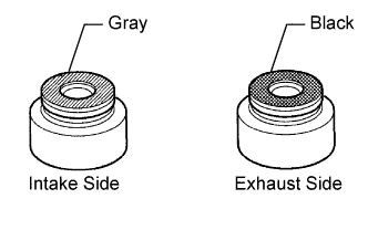
- NOTICE:
- Pay attention when installing the intake and exhaust oil seals. For example, installing the intake oil seal into the exhaust side or installing the exhaust oil seal to the intake side can cause installation problems later.
- HINT:
- The intake valve oil seals are gray and the exhaust valve oil seals are black.
Using SST, push in the oil seals.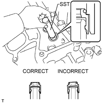
- SST
- 09201-41020
- NOTICE:
- Failure to use SST will cause the seal to be damaged or improperly seated.
| 23. INSTALL EXHAUST VALVE |
Apply a sufficient coat of engine oil to the tip area of the intake valve shown in the illustration.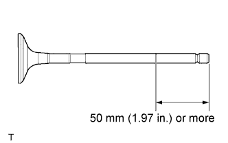
Install the valve, compression spring and spring retainer to the cylinder head.
- NOTICE:
- Install the same parts in the same combination to the original locations.
Using SST, compress the spring and install the 2 retainer locks.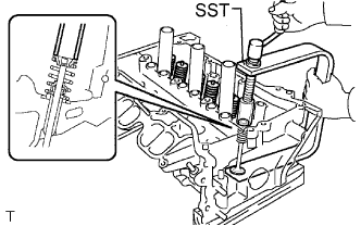
- SST
- 09202-70020
(09202-00010)
Using a plastic hammer, lightly tap the valve stem tip to ensure a proper fit.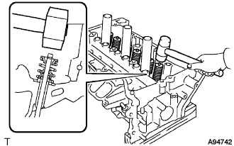
- NOTICE:
- Be careful not to damage the retainer.
| 24. INSTALL INTAKE VALVE |
Apply a sufficient coat of engine oil to the tip area of the intake valve shown in the illustration.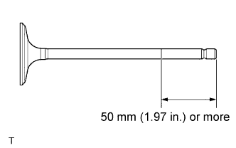
Install the valve, compression spring and spring retainer to the cylinder head.
- NOTICE:
- Install the same parts in the same combination to the original locations.
Using SST, compress the spring and install the 2 retainer locks.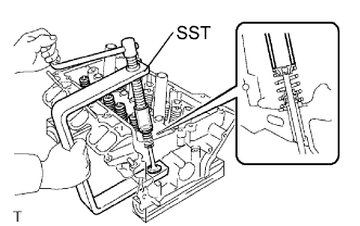
- SST
- 09202-70020
(09202-00010)
Using a plastic hammer, lightly tap the valve stem tip to ensure a proper fit.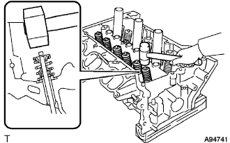
- NOTICE:
- Be careful not to damage the retainer.
| 25. INSTALL VALVE STEM CAP |
Apply a light coat of engine oil to the valve stem caps.
Install the valve stem caps on the valves.
| 26. INSTALL ENGINE REAR OIL SEAL |
Place the oil seal retainer on wooden blocks.
Using SST, tap in a new oil seal until its surface is flush with the oil seal retainer edge.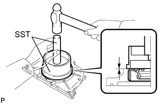
- SST
- 09223-15030
09950-70010 (09951-07100)
- NOTICE:
- Keep the lip free of foreign matter.
- Do not tap on the oil seal at an angle.
- Keep the lip free of foreign matter.
| 27. INSTALL ENGINE REAR OIL SEAL RETAINER |
Apply seal packing in a continuous line as shown in the illustration.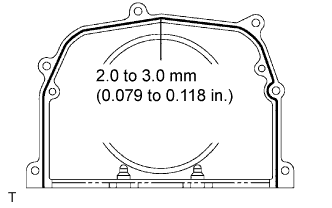
- Seal packing:
- Part No. 08826-00080 or equivalent
- Seal diameter:
- 2.0 to 3.0 mm (0.079 to 0.118 in.)
- NOTICE:
- Remove any oil from the contact surface.
- Install the oil seal retainer within 3 minutes after applying seal packing.
- Do not start the engine for at least 2 hours after installation.
- Remove any oil from the contact surface.
Install the oil seal retainer with the 6 bolts.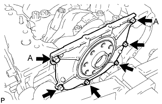
- Torque:
- 10 N*m{ 102 kgf*cm , 7 ft.*lbf }
- NOTICE:
- Be sure to apply adhesive 1324 to the bolts in the places indicated by A before installing them.
- Adhesive:
- Part No. 08833-00070, THREE BOND 1324 or equivalent
| 28. INSTALL WATER OUTLET PIPE SUB-ASSEMBLY |
Install the water outlet pipe with the 2 bolts.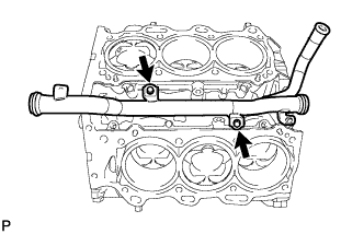
- Torque:
- 10 N*m{ 102 kgf*cm , 7 ft.*lbf }
| 29. INSTALL KNOCK SENSOR |
Install the 2 knock sensors with the 2 bolts as shown in the illustration.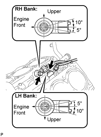
- Torque:
- 20 N*m{ 204 kgf*cm , 15 ft.*lbf }
Connect the 2 knock sensor connectors.
Connect the knock sensor wire clamp.
| 30. INSTALL CYLINDER BLOCK WATER JACKET SPACER RH |
Install the water jacket spacer as shown in the illustration.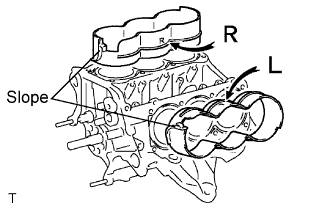
- HINT:
- Be sure to face the slope to the front of the engine.
| 31. INSTALL CYLINDER BLOCK WATER JACKET SPACER LH |
Install the water jacket spacer as shown in the illustration.
- HINT:
- Be sure to face the slope to the front of the engine.
| 32. INSTALL CYLINDER HEAD SUB-ASSEMBLY RH |
Apply a continuous line of seal packing to a new cylinder head gasket as shown in the illustration.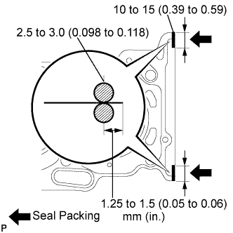
- Seal packing:
- Part No. 08826-00080 or equivalent
- Seal diameter:
- 2.5 to 3.0 mm (0.098 to 0.118 in.)
- NOTICE:
- Remove any oil from the contact surface.
- Install the cylinder head gasket within 3 minutes after applying the seal packing.
- Do not apply engine oil within 2 hours of installation.
- Remove any oil from the contact surface.
Place the cylinder head gasket on the cylinder block surface with the Lot No. stamp upward.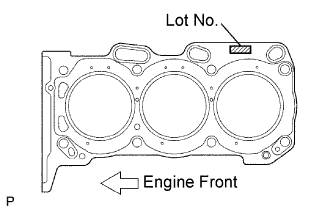
- NOTICE:
- Be careful of the installation direction.
- Gently place the cylinder head in order not to damage the gasket with the bottom part of the head.
- Be careful of the installation direction.
Place the cylinder head on the cylinder block.
- NOTICE:
- Be careful not to allow oil to adhere to the bottom part of the cylinder head.
- HINT:
- The cylinder head bolts are tightened in 3 progressive steps.
Apply a light coat of engine oil to the threads and under the heads of the cylinder head bolts.
Step 1
Using a 10 mm bi-hexagon wrench, install and uniformly tighten the 8 cylinder head bolts with the plate washers in several steps and in the sequence shown in the illustration.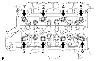
- Torque:
- 36 N*m{ 367 kgf*cm , 27 ft.*lbf }
Step 2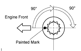
Mark the cylinder head bolt head with paint as shown in the illustration.
Tighten the cylinder head bolts another 90°.
Step 3
Tighten the cylinder head bolts by an additional 90°.
Check that the painted mark is now facing rearward.
Seal packing will seep out on the engine's front side. Thoroughly wipe off seeped out seal packing.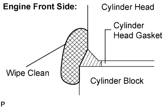
| 33. INSTALL CYLINDER HEAD SUB-ASSEMBLY LH |
Apply a continuous line of the seal packing to a new cylinder head gasket as shown in the illustration.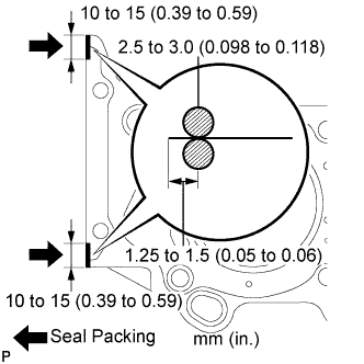
- Seal packing:
- Part No. 08826-00080 or equivalent
- Seal diameter:
- 2.5 to 3.0 mm (0.098 to 0.118 in.)
- NOTICE:
- Remove any oil from the contact surface.
- Install the cylinder head gasket within 3 minutes after applying the seal packing.
- Do not apply engine oil within 2 hours of installation.
- Remove any oil from the contact surface.
Place the cylinder head gasket on the cylinder block surface with the Lot No. stamp upward.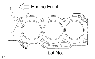
- NOTICE:
- Be careful of the installation direction.
- Gently place the cylinder head in order not to damage the gasket with the bottom part of the head.
- Be careful of the installation direction.
Place the cylinder head on the cylinder block.
- NOTICE:
- Be careful not to allow oil to adhere to the bottom part of the cylinder head.
- HINT:
- The cylinder head bolts are tightened in 3 progressive steps.
Apply a light coat of engine oil to the threads and under the heads of the cylinder head bolts.
Step 1
Using a 10 mm bi-hexagon wrench, install and uniformly tighten the 8 cylinder head bolts with the plate washers in several steps in the sequence shown in the illustration.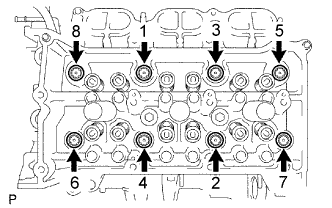
- Torque:
- 36 N*m{ 367 kgf*cm , 27 ft.*lbf }
Step 2
Mark the cylinder head bolt head with paint as shown in the illustration.
Tighten the cylinder head bolts by 90°.
Step 3
Tighten the cylinder head bolts by an additional 90°.
Check that the painted mark is now facing rearward.
Tighten the 2 bolts in the order shown in the illustration.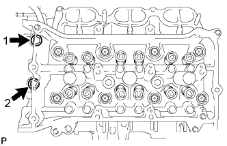
- Torque:
- 30 N*m{ 306 kgf*cm , 22 ft.*lbf }
Seal packing will seep out on the engine's front side. Thoroughly wipe off seeped out seal packing.
| 34. INSTALL VALVE LASH ADJUSTER ASSEMBLY |
- NOTICE:
- Keep the lash adjuster free of dirt and foreign objects.
- Only use clean engine oil.
- Keep the lash adjuster free of dirt and foreign objects.
Place the lash adjuster into a container filled with engine oil.
Insert the SST's tip into the lash adjuster's plunger and use the tip to press down on the check ball inside the plunger.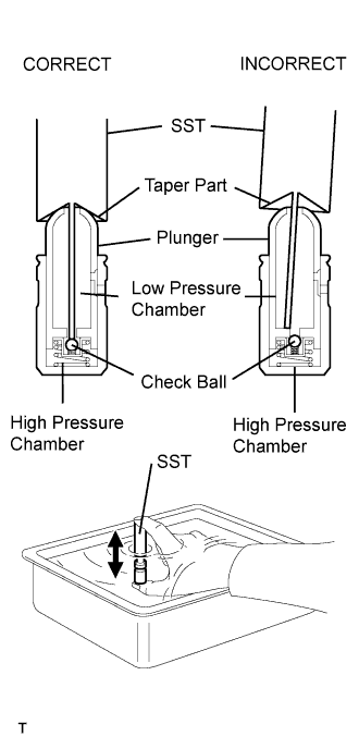
- SST
- 09276-75010
Squeeze the SST and lash adjuster together to move the plunger up and down 5 to 6 times.
Check the movement of the plunger and bleed the air.
- OK:
- Plunger moves up and down.
- NOTICE:
- When bleeding high-pressure air from the compression chamber, make sure that the tip of the SST is actually pressing the check ball as shown in the illustration. If the check ball is not pressed, air will not bleed.
After bleeding the air, remove SST. Then, try to quickly and firmly press the plunger with a finger.
- OK:
- Plunger is very difficult to move.
Install the lash adjusters.
- NOTICE:
- Install the lash adjuster to the same place it was removed from.
| 35. INSTALL NO. 1 VALVE ROCKER ARM SUB-ASSEMBLY |
Apply engine oil to the lash adjuster tip and valve stem cap end.
Make sure that the valve rocker arms are installed as shown in the illustration.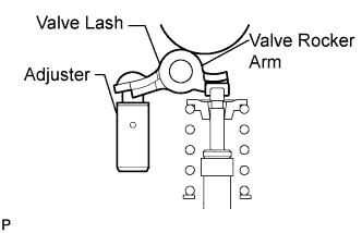
| 36. INSTALL CAMSHAFT BEARING CAP (for Bank 1) |
Apply engine oil to the camshaft journals, camshaft housing and bearing caps.
Install the camshaft and camshaft No. 2 to the camshaft housing RH.
Make sure of the marks and numbers on the camshaft bearing caps and place them in each proper position and direction.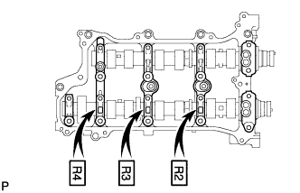
Temporarily tighten the 9 bolts in the order shown in the illustration.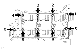
- Torque:
- 10 N*m{ 102 kgf*cm , 7 ft.*lbf }
| 37. INSTALL CAMSHAFT HOUSING SUB-ASSEMBLY RH |
Make sure that the valve rocker arm is installed as shown in the illustration.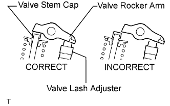
Apply seal packing in a continuous line as shown in the illustration.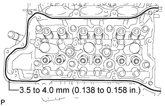
- Seal packing:
- Part No. 08826-00080 or equivalent
- Seal diameter:
- 3.5 to 4.0 mm (0.138 to 0.158 in.)
- NOTICE:
- Remove any oil from the contact surface.
- Install the camshaft housing sub-assembly RH within 3 minutes.
- Do not start the engine for at least 2 hours after installing.
- Remove any oil from the contact surface.
Install the camshaft housing RH and tighten the 14 bolts in the order shown in the illustration.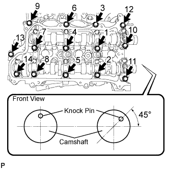
- Torque:
- 28 N*m{ 286 kgf*cm , 21 ft.*lbf }
- NOTICE:
- When installing the camshaft housing RH, it is necessary to correctly position the camshafts as shown in the illustration. Failure to correctly position these parts may result in damage due to contact between the pistons and valves. If a camshaft is rotated with a piston at TDC, valve contact will occur.
- If any of the bolts are loosened during installation, remove the camshaft housing, clean the installation surfaces, and reapply seal packing.
- If the camshaft housing is removed because any of the bolts are loosened during installation, make sure that the previously applied seal packing does not enter any oil passages.
- When installing the camshaft housing RH, it is necessary to correctly position the camshafts as shown in the illustration. Failure to correctly position these parts may result in damage due to contact between the pistons and valves. If a camshaft is rotated with a piston at TDC, valve contact will occur.
Tighten the 9 bolts in the order shown in the illustration.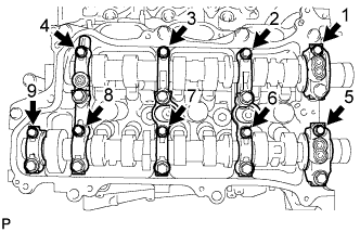
- Torque:
- 16 N*m{ 163 kgf*cm , 12 ft.*lbf }
| 38. INSTALL CAMSHAFT BEARING CAP (for Bank 2) |
Apply engine oil to the camshaft journals, camshaft housing and bearing caps.
Install the camshaft No. 3 and camshaft No. 4 to the camshaft housing LH.
Make sure of the marks and numbers on the camshaft bearing caps and place them in each proper position and direction.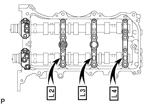
Temporarily tighten the 8 bolts in the order shown in the illustration.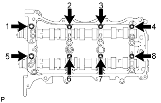
- Torque:
- 10 N*m{ 102 kgf*cm , 7 ft.*lbf }
| 39. INSTALL CAMSHAFT HOUSING SUB-ASSEMBLY LH |
Make sure that the valve rocker arm is installed as shown in the illustration.
Apply seal packing in a continuous line as shown in the illustration.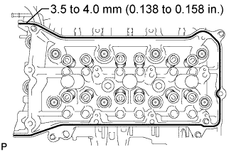
- Seal packing:
- Part No. 08826-00080 or equivalent
- Seal diameter:
- 3.5 to 4.0 mm (0.138 to 0.158 in.)
- NOTICE:
- Remove any oil from the contact surface.
- Install the camshaft housing sub-assembly LH within 3 minutes.
- Do not start the engine for at least 2 hours after installing.
- Remove any oil from the contact surface.
Install the camshaft housing LH and tighten the 13 bolts in the order shown in the illustration.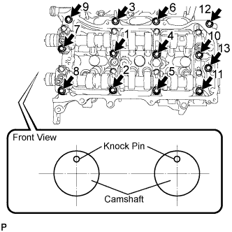
- Torque:
- 28 N*m{ 286 kgf*cm , 21 ft.*lbf }
- NOTICE:
- When installing the camshaft housing LH, it is necessary to correctly position the camshafts as shown in the illustration. Failure to correctly position these parts may result in damage due to contact between the pistons and valves. If a camshaft is rotated with a piston at TDC, valve contact will occur.
- If any of the bolts are loosened during installation, remove the camshaft housing, clean the installation surfaces, and reapply seal packing.
- If the camshaft housing is removed because any of the bolts are loosened during installation, make sure that the previously applied seal packing does not enter any oil passages.
- When installing the camshaft housing LH, it is necessary to correctly position the camshafts as shown in the illustration. Failure to correctly position these parts may result in damage due to contact between the pistons and valves. If a camshaft is rotated with a piston at TDC, valve contact will occur.
Tighten the 8 bolts in the order shown in the illustration.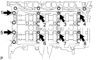
- Torque:
- 16 N*m{ 163 kgf*cm , 12 ft.*lbf }
| 40. INSTALL NO. 2 CHAIN TENSIONER ASSEMBLY |
Install the No. 2 chain tensioner with the bolt.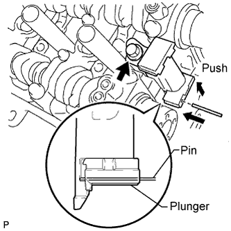
- Torque:
- 21 N*m{ 214 kgf*cm , 15 ft.*lbf }
While pushing in the tensioner, insert a pin of φ 1.0 mm (0.039 in.) into the hole to fix it.
| 41. INSTALL CAMSHAFT TIMING GEARS AND NO. 2 CHAIN (for Bank 1) |
Align the mark plate (yellow) with the timing marks (1-dot mark) of the camshaft timing gears as shown in the illustration.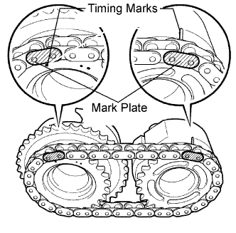
Apply a light coat of engine oil to the bolt threads and bolt-seating surface.
Align the knock pin of the camshaft with the pin hole of the camshaft timing gear. Install the camshaft timing gear and camshaft timing exhaust gear RH with the No. 2 chain installed.
Hold the hexagonal portion of the camshaft with a wrench, and tighten the 2 bolts.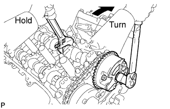
- Torque:
- 100 N*m{ 1,020 kgf*cm , 74 ft.*lbf }
Remove the pin from the chain tensioner.
| 42. INSTALL NO. 3 CHAIN TENSIONER ASSEMBLY |
Install the chain tensioner with the bolt.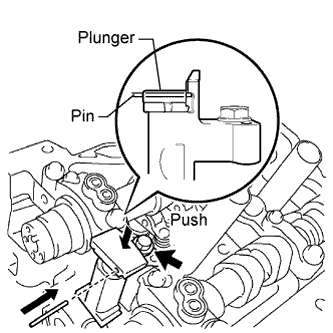
- Torque:
- 21 N*m{ 214 kgf*cm , 15 ft.*lbf }
While pushing in the tensioner, insert a pin of φ 1.0 mm (0.039 in.) into the hole to hold it.
| 43. INSTALL CAMSHAFT TIMING GEARS AND NO. 2 CHAIN (for Bank 2) |
Align the mark plate (yellow) with the timing marks (2-dot mark) of the camshaft timing gears as shown in the illustration.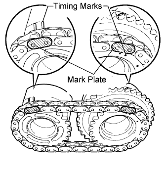
Apply a light coat of engine oil to the bolt threads and bolt-seating surface.
Align the knock pin of the camshaft with the pin hole of the camshaft timing gear. Install the camshaft timing gear and camshaft timing exhaust gear LH with the No. 2 chain installed.
Hold the hexagonal portion of the camshaft with a wrench, and tighten the 2 bolts.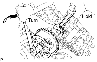
- Torque:
- 100 N*m{ 1,020 kgf*cm , 74 ft.*lbf }
Remove the pin from the chain tensioner.
| 44. INSTALL NO. 1 CHAIN VIBRATION DAMPER |
Install the chain vibration damper with the 2 bolts.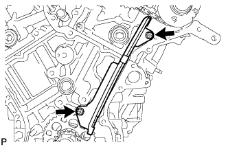
- Torque:
- 23 N*m{ 230 kgf*cm , 17 ft.*lbf }
| 45. INSTALL NO. 2 CHAIN VIBRATION DAMPER |
Install the 2 chain vibration dampers.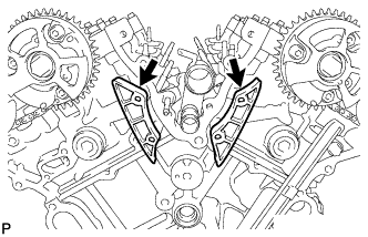
| 46. INSTALL CRANKSHAFT TIMING SPROCKET |
Install the 2 timing gear set keys and timing gear as shown in the illustration.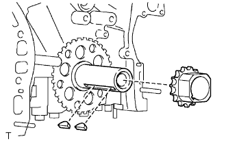
| 47. INSTALL IDLE SPROCKET ASSEMBLY |
Apply a light coat of engine oil to the rotating surface of the No. 1 idle gear shaft.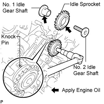
Temporarily install the No. 1 idle gear shaft and idle sprocket with the No. 2 idle gear shaft while aligning the knock pin of the No. 1 idle gear with the knock pin groove of the cylinder block.
- NOTICE:
- Be careful of the idle gear direction.
- HINT:
- Check that no foreign objects are on the idle gear shafts No. 1 and No. 2.
Using a 10 mm hexagon wrench, tighten the No. 2 idle gear shaft.
- Torque:
- 60 N*m{ 612 kgf*cm , 44 ft.*lbf }
- HINT:
- After installing the idle sprocket assembly, check that the idle sprocket turns smoothly.
| 48. INSTALL CHAIN SUB-ASSEMBLY |
Align the mark plate and timing mark as shown in the illustration and install the chain.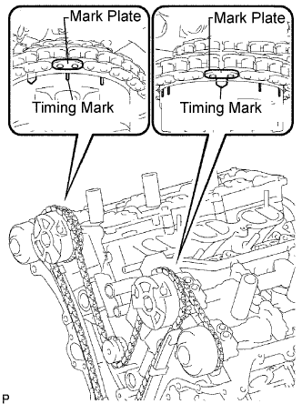
- HINT:
- The camshaft mark plate is orange.
Do not pass the chain over the crankshaft, just put it on it.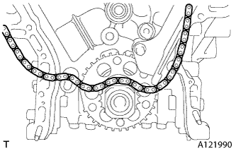
Turn the camshaft timing gear assembly on the RH bank counterclockwise to tighten the chain between the banks.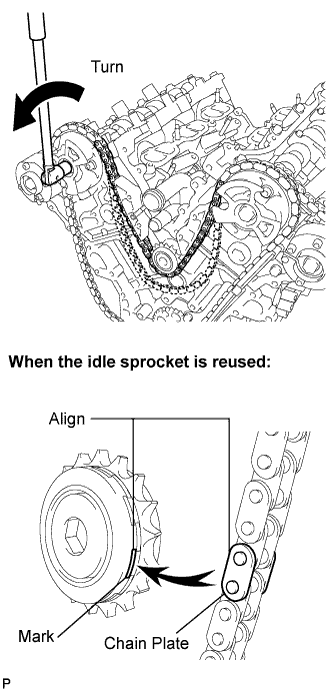
- NOTICE:
- When the idle sprocket is reused, align the chain plate with the mark where the plate had been in order to tighten the chain between the banks.
Align the mark plate and timing mark as shown in the illustration and install the chain onto the crankshaft timing sprocket.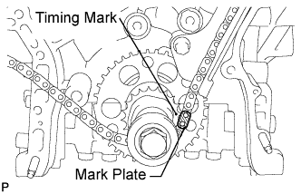
- HINT:
- The crankshaft mark plate is yellow.
Temporarily tighten the pulley set bolt.
Turn the crankshaft clockwise to set it to the RH block bore center line (TDC / compression).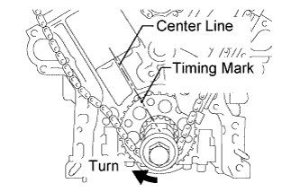
| 49. INSTALL CHAIN TENSIONER SLIPPER |
Install the chain tensioner slipper.
| 50. INSTALL NO. 1 CHAIN TENSIONER ASSEMBLY |
Move the stopper plate upward to release the lock, and push the plunger deep into the tensioner.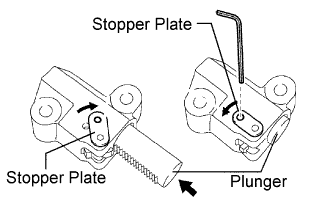
Move the stopper plate downward to set the lock, and insert a hexagon wrench into the hole of the stopper plate.
Install the chain tensioner with the 2 bolts.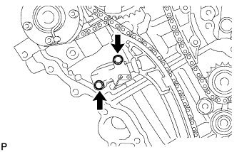
- Torque:
- 10 N*m{ 102 kgf*cm , 7 ft.*lbf }
Remove the lock pin of the chain tensioner. Check that each timing mark is aligned with the crankshaft at the TDC / compression.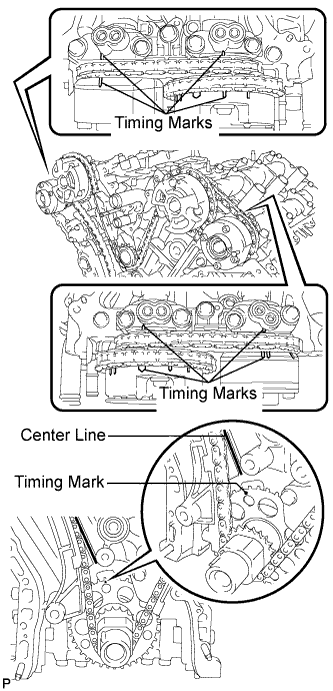
Remove the pulley set bolt.
| 51. INSTALL TIMING CHAIN CASE OIL SEAL |
Using SST, tap in a new oil seal until its surface is flush with the timing gear case edge.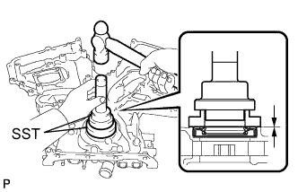
- SST
- 09223-22010
09506-35010
- NOTICE:
- Keep the lip free of foreign matter.
- Do not tap on the oil seal at an angle.
- Make sure that the oil seal edge does not stick out of the timing chain case.
- Keep the lip free of foreign matter.
| 52. INSTALL WATER PUMP ASSEMBLY |
Install a new gasket and the water pump with the 16 bolts.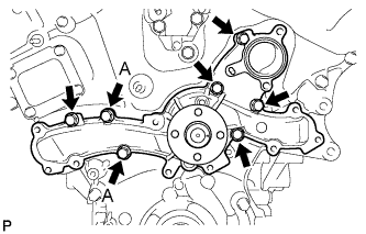
- Torque:
- 9.1 N*m{ 93 kgf*cm , 81 in.*lbf }
- NOTICE:
- Be sure to replace the bolts indicated by A with new ones or reuse them after applying adhesive 1344.
| 53. INSTALL TIMING CHAIN COVER SUB-ASSEMBLY |
Apply seal packing in a continuous line to the engine unit as shown in the following illustration.
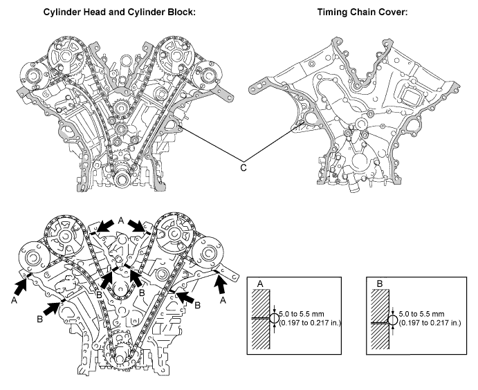
- Seal packing:
- Part No. 08826-00080 or equivalent
- Seal diameter:
- 5.0 to 5.5 mm (0.197 to 0.217 in.)
- NOTICE:
- Be sure to clean and degrease the contact surfaces, especially the surfaces indicated by C in the illustration.
- When the contact surfaces are wet, wipe them with an oil-free cloth before applying seal packing.
- Install the chain cover within 3 minutes.
- Do not start the engine for at least 2 hours after installing.
- Be sure to clean and degrease the contact surfaces, especially the surfaces indicated by C in the illustration.
Apply seal packing in a continuous line to the timing chain cover as shown in the following illustration.
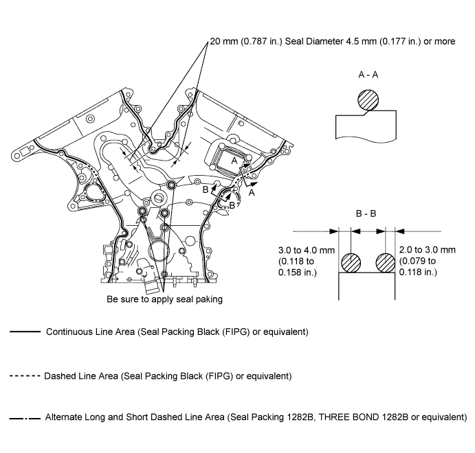
- Seal packing:
- 08826-00080 or equivalent
- 08826-00100, THREE BOND 1282B or equivalent
- NOTICE:
- When the contact surfaces are wet, wipe them with an oil-free cloth before applying seal packing.
- Install the chain cover within 3 minutes and tighten the bolts within 15 minutes after applying seal packing.
- Do not start the engine for at least 2 hours after installing.
- When the contact surfaces are wet, wipe them with an oil-free cloth before applying seal packing.
- Apply seal packing as follows:
Area
Seal Packing Diameter
Application Position from Inside Seal Line
Continuous Line Area
3.5 to 4.0 mm (0.138 to 0.158 in.)
3.0 to 4.0 mm (0.118 to 0.158 in.)
Alternate Long and Dashed Line Area
3.5 to 4.0 mm (0.138 to 0.158 in.)
2.0 to 3.0 mm (0.079 to 0.118 in.)
Dashed Line Area
6.0 mm (0.236 in.)
-
Install a new gasket.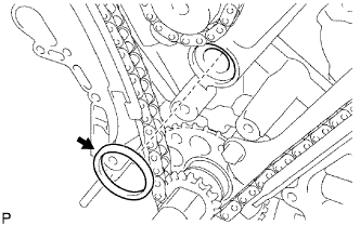
Align the oil pump's drive rotor spline and the crankshaft as shown in the illustration. Install the spline and chain cover to the crankshaft.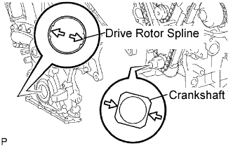
Temporarily tighten the timing chain cover with the 25 bolts and 2 nuts.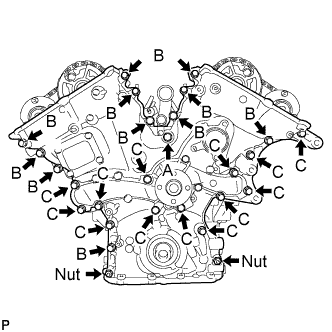
- Bolt length:
Item
Length
Bolt A
50 mm (1.97 in.)
Bolt B
25 mm (0.98 in.)
Bolt C
55 mm (2.17 in.)
- NOTICE:
- Make sure that there is no oil on the bolt threads.
Fully tighten the 3 bolts as shown in the illustration.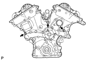
- Torque:
- 43 N*m{ 438 kgf*cm , 32 ft.*lbf } for bolt A
- 21 N*m{ 214 kgf*cm , 15 ft.*lbf } for bolts except A
Fully tighten the 3 bolts as shown in the illustration.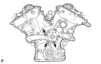
- Torque:
- 21 N*m{ 214 kgf*cm , 15 ft.*lbf }
Fully tighten the 7 bolts and 2 nuts as shown in the illustration.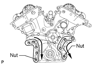
- Torque:
- 21 N*m{ 214 kgf*cm , 15 ft.*lbf }
- HINT:
- Tighten the bolts and nuts in the order of upper to lower as shown in the illustration.
Fully tighten the 12 bolts as shown in the illustration.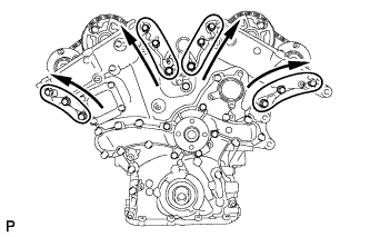
- Torque:
- 21 N*m{ 214 kgf*cm , 15 ft.*lbf }
- HINT:
- Tighten the bolts in the order of lower to upper as shown in the illustration.
Install a new gasket and the chain cover plate with the 4 bolts.
- Torque:
- 9.1 N*m{ 93 kgf*cm , 81 in.*lbf }
| 54. INSTALL OIL STRAINER SUB-ASSEMBLY |
Using an E6 "torx" socket, install the stud bolts as shown in the illustration.
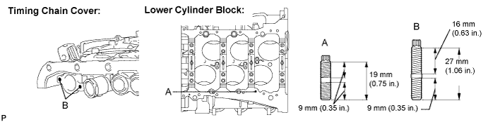
- Torque:
- 4.0 N*m{ 41 kgf*cm , 35 in.*lbf }
Install the baffle plate with the 8 bolts.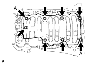
- Torque:
- 10 N*m{ 102 kgf*cm , 7 ft.*lbf }
- HINT:
- Temporarily tighten the 8 bolts. Fully tighten 2 bolts A as shown in the illustration before tightening the other bolts.
Install a new gasket and the oil strainer with the 3 nuts.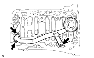
- Torque:
- 10 N*m{ 102 kgf*cm , 7 ft.*lbf }
Install 2 new O-rings.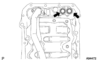
| 55. INSTALL OIL PAN SUB-ASSEMBLY |
When replacing a stud bolt, install it by using an E6 "torx" socket wrench.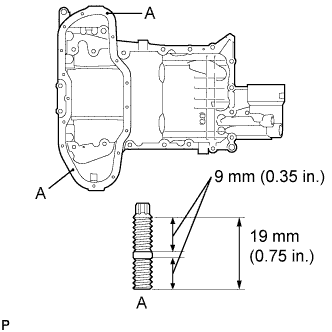
- Torque:
- 4.0 N*m{ 41 kgf*cm , 35 in.*lbf }
Apply seal packing in a continuous line as shown in the illustration.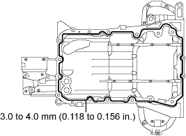
- Seal packing:
- Part No. 08826-00080 or equivalent
- Seal diameter:
- 3.0 to 4.0 mm (0.118 to 0.156 in.)
- NOTICE:
- Remove any oil from the contact surface.
- Install the oil pan within 3 minutes after applying seal packing.
- Do not start the engine for at least 2 hours after installing.
- Remove any oil from the contact surface.
Install the oil pan with the 16 bolts and 2 nuts.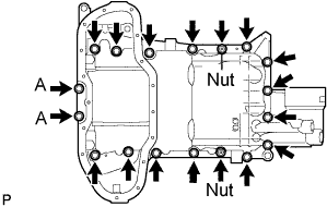
- Torque:
- 10 N*m{ 102 kgf*cm , 7 ft.*lbf } for bolt A
- 21 N*m{ 214 kgf*cm , 15 ft.*lbf } for bolts except A
| 56. INSTALL NO. 2 OIL PAN SUB-ASSEMBLY |
Apply seal packing in a continuous line as shown in the illustration.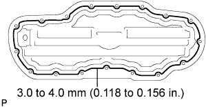
- Seal packing:
- Part No. 08826-00080 or equivalent
- Seal diameter:
- 3.0 to 4.0 mm (0.118 to 0.156 in.)
- NOTICE:
- Remove any oil from the contact surface.
- Install the oil pan No. 2 within 3 minutes after applying seal packing.
- Do not start the engine for at least 2 hours after installing.
- Remove any oil from the contact surface.
Install the oil pan with the 15 bolts and 2 nuts.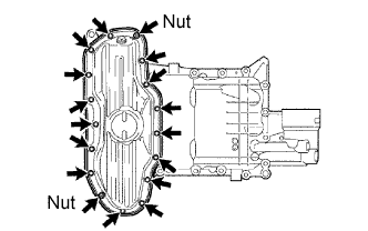
- Torque:
- 10 N*m{ 102 kgf*cm , 7 ft.*lbf }
| 57. INSTALL OIL PAN DRAIN PLUG |
Install a new gasket and the drain plug.
- Torque:
- 40 N*m{ 408 kgf*cm , 30 ft.*lbf }
| 58. INSTALL SPARK PLUG TUBE GASKET |
Using a cutter, cut off the sealing part of the removed plug tube gasket.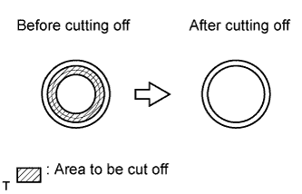
Using a plug tube gasket which has had the sealing part cut off, uniformly press in a new plug tube gasket all the way.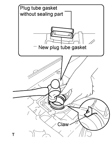
- NOTICE:
- Keep the lip free of foreign matter.
- Do not tap on the oil seal at an angle.
- Keep the lip free of foreign matter.
- HINT:
- If a plug tube gasket that will be used to install a new gasket is deformed, and cannot be positioned on a new gasket, correct the deformation using pliers.
Return the claws of the ventilation baffle plate to their original positions.
| 59. INSTALL CYLINDER HEAD COVER SUB-ASSEMBLY (for Bank 1) |
Apply seal packing as shown in the illustration.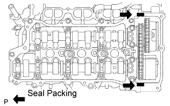
- Seal packing:
- 08826-00080 or equivalent
- NOTICE:
- Remove any oil from the contact surface.
- Install the head cover within 3 minutes after applying seal packing.
- Do not start the engine for at least 2 hours after installing.
- Remove any oil from the contact surface.
Install 3 new gaskets as shown in the illustration.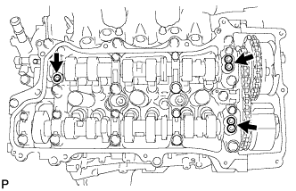
Install a new gasket to the head cover.
Install a head cover with the 14 bolts.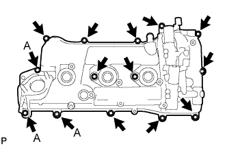
- Torque:
- 21 N*m{ 214 kgf*cm , 15 ft.*lbf } for bolt A
- 10 N*m{ 102 kgf*cm , 7 ft.*lbf } for bolts except A
| 60. INSTALL CYLINDER HEAD COVER SUB-ASSEMBLY (for Bank 2) |
Apply seal packing as shown in the illustration.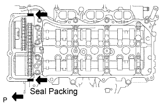
- Seal packing:
- 08826-00080 or equivalent
- NOTICE:
- Remove any oil from the contact surface.
- Install the head cover within 3 minutes after applying seal packing.
- Do not start the engine for at least 2 hours after installing.
- Remove any oil from the contact surface.
Install 3 new gaskets as shown in the illustration.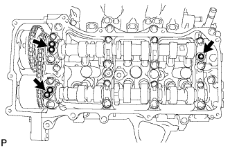
Install a new gasket to the head cover.
Install the head cover with the 12 bolts.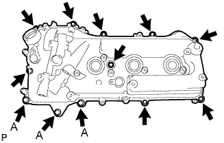
- Torque:
- 21 N*m{ 214 kgf*cm , 15 ft.*lbf } for bolt A
- 10 N*m{ 102 kgf*cm , 7 ft.*lbf } for bolts except A
| 61. INSTALL REAR WATER BY-PASS JOINT |
Install 2 new gaskets and a new O-ring.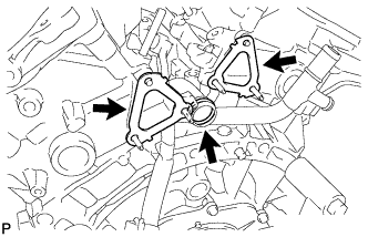
- HINT:
- Apply soapy water to the O-ring.
Install the water by-pass joint with the 2 bolts and 4 nuts.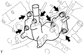
- Torque:
- 10 N*m{ 102 kgf*cm , 7 ft.*lbf }
- NOTICE:
- Be careful that the O-ring does not get caught between the parts.
| 62. INSTALL WATER INLET WITH THERMOSTAT SUB-ASSEMBLY |
Install a new gasket and water inlet with thermostat with the 3 nuts.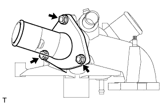
- Torque:
- 10 N*m{ 102 kgf*cm , 7 ft.*lbf }
| 63. INSTALL WATER INLET SUB-ASSEMBLY |
Install the 3 water by-pass hoses.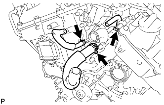
Install 2 new O-rings.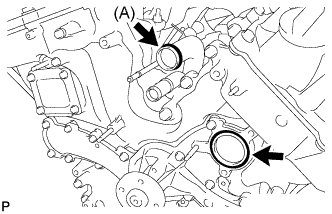
- HINT:
- Apply a small amount of water or soapy water to O-ring (A) in the illustration before installing it.
Install the water inlet with the 4 bolts and nut.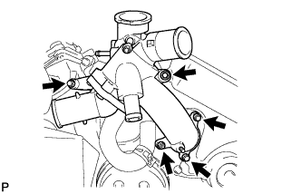
- Torque:
- 10 N*m{ 102 kgf*cm , 7 ft.*lbf }
- NOTICE:
- Be careful that the O-ring does not get caught between the parts.
Install the 3 water by-pass hoses.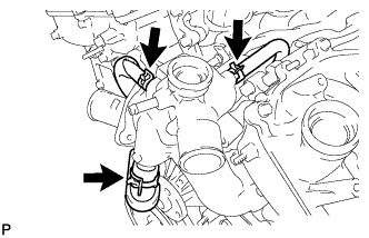
| 64. INSTALL CRANKSHAFT PULLEY |
Align the pulley set key with the key groove of the pulley, and slide on the pulley.
Using SST, install the pulley bolt.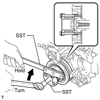
- SST
- 09213-70011
(09213-70020)
09330-00021
- Torque:
- 250 N*m{ 2,550 kgf*cm , 184 ft.*lbf }
| 65. INSTALL OIL FILTER ELEMENT |
Clean the inside of the oil filter cap, the threads and O-ring groove.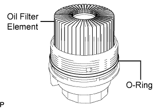
Apply a light coat of engine oil to a new O-ring and install it to the oil filter cap.
Set a new oil filter element to the oil filter cap.
Remove any dirt or foreign matter from the installation surface of the engine.
Apply a light coat of engine oil to the O-ring again and install the oil filter cap.
- NOTICE:
- Be careful that the O-ring does not get caught between the parts.
Using SST, tighten the oil filter cap.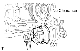
- SST
- 09228-06501
- Torque:
- 25 N*m{ 255 kgf*cm , 18 ft.*lbf }
- NOTICE:
- Make sure that the oil filter is installed securely as shown in the illustration.
| 66. INSTALL CYLINDER BLOCK WATER DRAIN COCK SUB-ASSEMBLY |
Apply adhesive around the drain cocks.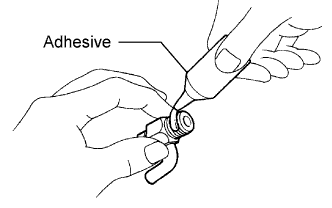
- Adhesive:
- Part No. 08833-00070, THREE BOND 1324 or equivalent
Install the water drain cocks as shown in the illustration.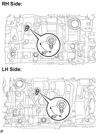
- Torque:
- 30 N*m{ 306 kgf*cm , 22 ft.*lbf }
- NOTICE:
- Do not rotate the drain cocks more than 1 revolution (360°) after tightening the drain cocks with the specified torque.
Install the water drain cock plugs to the water drain cocks.
- Torque:
- 13 N*m{ 130 kgf*cm , 9 ft.*lbf }
| 67. INSTALL NO. 1 OIL PIPE |
Make sure that there is no foreign matter on the mesh of the oil control valve filter LH.
- NOTICE:
- Do not touch the mesh when installing the oil control valve filter.
Install the oil control valve filter LH to the oil pipe union. Install new gaskets and temporarily install the oil pipe (on the head cover side).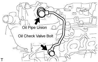
Install a new gasket and temporarily install the oil pipe (on the cylinder head side) with the oil check valve bolt.
Tighten the oil pipe union (on the head cover side).
- Torque:
- 60 N*m{ 612 kgf*cm , 44 ft.*lbf }
Tighten the oil check valve bolt (on the cylinder head side).
- Torque:
- 60 N*m{ 612 kgf*cm , 44 ft.*lbf }
- NOTICE:
- If the link that connects the gaskets is broken, remove the connecting link by using nippers or similar tools.
| 68. INSTALL NO. 2 OIL PIPE |
Make sure that there is no foreign matter on the mesh of the oil control valve filter RH.
- NOTICE:
- Do not touch the mesh when installing the oil control valve filter.
Install the oil control valve filter RH to the oil pipe union. Install new gaskets and temporarily install the oil pipe (on the head cover side).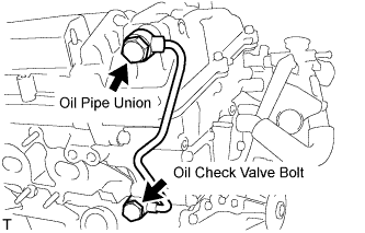
Install a new gasket and temporarily install the oil pipe (on the cylinder head side) with the oil check valve bolt.
Tighten the oil pipe union (on the head cover side).
- Torque:
- 60 N*m{ 612 kgf*cm , 44 ft.*lbf }
Tighten the oil check valve bolt (on the cylinder head side).
- Torque:
- 60 N*m{ 612 kgf*cm , 44 ft.*lbf }
- NOTICE:
- If the link that connects the gaskets is broken, remove the connecting link by using nippers or similar tools.
| 69. INSTALL CRANKSHAFT POSITION SENSOR |
Install the sensor with the bolt.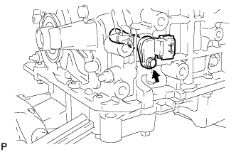
- Torque:
- 10 N*m{ 102 kgf*cm , 7 ft.*lbf }
| 70. INSTALL CAMSHAFT TIMING OIL CONTROL VALVE ASSEMBLY |
Install the 4 oil control valves with the 4 bolts.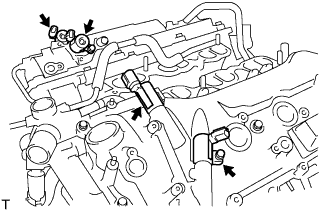
- Torque:
- 10 N*m{ 102 kgf*cm , 7 ft.*lbf }
| 71. INSTALL CAMSHAFT POSITION SENSOR |
Install the 4 sensors with the 4 bolts.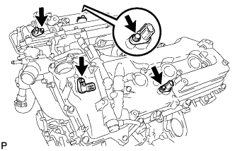
- Torque:
- 10 N*m{ 102 kgf*cm , 7 ft.*lbf }
| 72. INSTALL VENTILATION VALVE SUB-ASSEMBLY |
Apply adhesive around the ventilation valve.
- Adhesive:
- Part No. 08833-00070, THREE BOND 1324 or equivalent
Install the ventilation valve.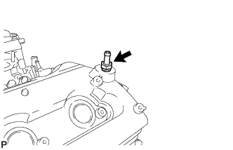
- Torque:
- 27 N*m{ 275 kgf*cm , 20 ft.*lbf }
| 73. INSTALL SPARK PLUG |
Install the spark plugs.
- Torque:
- 25 N*m{ 255 kgf*cm , 18 ft.*lbf }
| 74. INSTALL RADIATOR CAP SUB-ASSEMBLY |
Install the radiator cap.
| 75. INSTALL OIL FILLER CAP SUB-ASSEMBLY |
Install a new gasket.
Install the oil filler cap.