TERMINALS OF ECU
System information
| INSPECT FRONT POWER SEAT SWITCH LH (POSITION CONTROL ECU) |
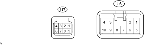

Disconnect the U7 and U6 ECU connectors.
Measure the voltage and resistance according to the value(s) in the table below.
If the result is not as specified, there may be a malfunction on the wire harness side.Symbols (Terminal No.)
Wiring Color
Terminal Description
Condition
Specified Condition
IG (U7-4) - GND (U6-1)
Y - W-B
Engine switch signal
Engine switch off
Below 1 V
IG (U7-4) - GND (U6-1)
Y - W-B
Engine switch signal
Engine switch on (IG)
10 to 14 V
+B (U6-5) - GND (U6-1)
L - W-B
Power source
Always
10 to 14 V
SYSB (U7-8) - GND (U6-1)
LG - W-B
System power source
Always
10 to 14 V
GND (U6-1) - Body ground
W-B - Body ground
Ground
Always
Below 1 Ω
Reconnect the U7 and U6 ECU connectors.
Measure the voltage according to the value(s) in the table below.
If the result is not as specified, the front power seat switch LH (position control ECU) may have a malfunction.Symbols (Terminal No.)
Wiring Color
Terminal Description
Condition
Specified Condition
SLD+ (U6-2) - GND (U6-1)
B - W-B
Sliding motor signal (forward)
Slide switch OFF
Below 1 V
SLD+ (U6-2) - GND (U6-1)
B - W-B
Sliding motor signal (forward)
Slide switch FRONT ON
10 to 14 V
SLD- (U6-3) - GND (U6-1)
G - W-B
Sliding motor signal (rearward)
Slide switch OFF
Below 1 V
SLD- (U6-3) - GND (U6-1)
G - W-B
Sliding motor signal (rearward)
Slide switch REAR ON
10 to 14 V
FRV+ (U6-6) - GND (U6-1)
W - W-B
Front vertical motor signal (upward)
Front vertical switch OFF
Below 1 V
FRV+ (U6-6) - GND (U6-1)
W - W-B
Front vertical motor signal (upward)
Front vertical switch UP ON
10 to 14 V
FRV- (U6-4) - GND (U6-1)
R - W-B
Front vertical motor signal (downward)
Front vertical switch OFF
Below 1 V
FRV- (U6-4) - GND (U6-1)
R - W-B
Front vertical motor signal (downward)
Front vertical switch DOWN ON
10 to 14 V
LFT+ (U6-7) - GND (U6-1)
Y - W-B
Lifter motor signal (upward)
Lifter switch OFF
Below 1 V
LFT+ (U6-7) - GND (U6-1)
Y - W-B
Lifter motor signal (upward)
Lifter switch UP ON
10 to 14 V
LFT- (U6-9) - GND (U6-1)
LG - W-B
Lifter motor signal (downward)
Lifter switch OFF
Below 1 V
LFT- (U6-9) - GND (U6-1)
LG - W-B
Lifter motor signal (downward)
Lifter switch DOWN ON
10 to 14 V
RCL+ (U6-8) - GND (U6-1)
BR - W-B
Reclining motor signal (forward)
Reclining switch OFF
Below 1 V
RCL+ (U6-8) - GND (U6-1)
BR - W-B
Reclining motor signal (forward)
Reclining switch FRONT ON
10 to 14 V
RCL- (U6-10) - GND (U6-1)
GR - W-B
Reclining motor signal (rearward)
Reclining switch OFF
Below 1 V
RCL- (U6-10) - GND (U6-1)
GR - W-B
Reclining motor signal (rearward)
Reclining switch REAR ON
10 to 14 V
| INSPECT FRONT POWER SEAT SWITCH RH (POSITION CONTROL ECU) |
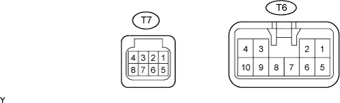
Disconnect the T6 and T7 ECU connectors.
Measure the voltage and resistance according to the value(s) in the table below.
If the result is not as specified, there may be a malfunction on the wire harness side.Symbols (Terminal No.)
Wiring Color
Terminal Description
Condition
Specified Condition
IG (T7-4) - GND (T6-1)
B - W-B
Engine switch signal
Engine switch off
Below 1 V
IG (T7-4) - GND (T6-1)
B - W-B
Engine switch signal
Engine switch on (IG)
10 to 14 V
+B (T6-5) - GND (T6-1)
L - W-B
Power source
Always
10 to 14 V
SYSB (T7-8) - GND (T6-1)
P - W-B
System power source
Always
10 to 14 V
GND (T6-1) - Body ground
W-B - Body ground
Ground
Always
Below 1 Ω
Reconnect the T6 and T7 ECU connectors.
Measure the voltage according to the value(s) in the table below.
If the result is not as specified, the front power seat switch RH (position control ECU) may have a malfunction.Symbols (Terminal No.)
Wiring Color
Terminal Description
Condition
Specified Condition
SLD+ (T6-2) - GND (T6-1)
B - W-B
Sliding motor signal (forward)
Slide switch OFF
Below 1 V
SLD+ (T6-2) - GND (T6-1)
B - W-B
Sliding motor signal (forward)
Slide switch FRONT ON
10 to 14 V
SLD- (T6-3) - GND (T6-1)
G - W-B
Sliding motor signal (rearward)
Slide switch OFF
Below 1 V
SLD- (T6-3) - GND (T6-1)
G - W-B
Sliding motor signal (rearward)
Slide switch REAR ON
10 to 14 V
FRV+ (T6-6) - GND (T6-1)
W - W-B
Front vertical motor signal (upward)
Front vertical switch OFF
Below 1 V
FRV+ (T6-6) - GND (T6-1)
W - W-B
Front vertical motor signal (upward)
Front vertical switch UP ON
10 to 14 V
FRV- (T6-4) - GND (T6-1)
R - W-B
Front vertical motor signal (downward)
Front vertical switch OFF
Below 1 V
FRV- (T6-4) - GND (T6-1)
R - W-B
Front vertical motor signal (downward)
Front vertical switch DOWN ON
10 to 14 V
LFT+ (T6-7) - GND (T6-1)
Y - W-B
Lifter motor signal (upward)
Lifter switch OFF
Below 1 V
LFT+ (T6-7) - GND (T6-1)
Y - W-B
Lifter motor signal (upward)
Lifter switch UP ON
10 to 14 V
LFT- (T6-9) - GND (T6-1)
LG - W-B
Lifter motor signal (downward)
Lifter switch OFF
Below 1 V
LFT- (T6-9) - GND (T6-1)
LG - W-B
Lifter motor signal (downward)
Lifter switch DOWN ON
10 to 14 V
RCL+ (T6-8) - GND (T6-1)
BR - W-B
Reclining motor signal (forward)
Reclining switch OFF
Below 1 V
RCL+ (T6-8) - GND (T6-1)
BR - W-B
Reclining motor signal (forward)
Reclining switch FRONT ON
10 to 14 V
RCL- (T6-10) - GND (T6-1)
GR - W-B
Reclining motor signal (rearward)
Reclining switch OFF
Below 1 V
RCL- (T6-10) - GND (T6-1)
GR - W-B
Reclining motor signal (rearward)
Reclining switch REAR ON
10 to 14 V
| CHECK OUTER MIRROR CONTROL ECU LH |
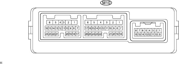
Disconnect the M10 ECU connector.
Measure the voltage and resistance according to the value(s) in the table below.
If the result is not as specified, there may be a malfunction on the wire harness side.Symbols (Terminal No.)
Wiring Color
Terminal Description
Condition
Specified Condition
GND (M10-1) - Body ground
W-B - Body ground
Ground
Always
Below 1 Ω
CPUB (M10-4) - GND (M10-1)
G - W-B
Battery (ECU power source)
Always
10 to 14 V
SIG (M10-3) - GND (M10-1)
B - W-B
Engine switch (IG) power supply
Engine switch off
Below 1 V
SIG (M10-3) - GND (M10-1)
B - W-B
Engine switch (IG) power supply
Engine switch on (IG)
10 to 14 V
BDR (M10-6) - GND (M10-1)
L - W-B
Battery (ECU power source)
Always
10 to 14 V
Reconnect the M10 ECU connector.
Measure the resistance according to the value(s) in the table below.
If the result is not as specified, the outer mirror control ECU LH may have a malfunction.Symbols (Terminal No.)
Wiring Color
Terminal Description
Condition
Specified Condition
MSWE (M10-26) - GND (M10-1)
O - W-B
Ground for seat memory switch
Always
Below 1 Ω
MM (M10-25) - MSWE (M10-26)
W - O
SET switch signal
SET switch OFF
10 to 14 V
MM (M10-25) - MSWE (M10-26)
W - O
SET switch signal
SET switch ON
Below 1 V
M1 (M10-22) - MSWE (M10-26)
LG - O
M1 switch signal
M1 switch OFF
10 to 14 V
M1 (M10-22) - MSWE (M10-26)
LG - O
M1 switch signal
M1 switch ON
Below 1 V
M2 (M10-23) - MSWE (M10-26)
R - O
M2 switch signal
M2 switch OFF
10 to 14 V
M2 (M10-23) - MSWE (M10-26)
R - O
M2 switch signal
M2 switch ON
Below 1 V
M3 (M10-24) - MSWE (M10-26)
Y - O
M3 switch signal
M3 switch OFF
10 to 14 V
M3 (M10-24) - MSWE (M10-26)
Y - O
M3 switch signal
M3 switch ON
Below 1 V
| CHECK OUTER MIRROR CONTROL ECU RH |
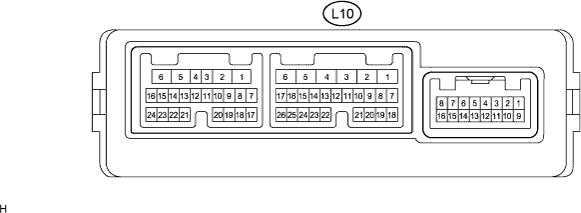
Disconnect the L10 ECU connector.
Measure the voltage and resistance according to the value(s) in the table below.
If the result is not as specified, there may be a malfunction on the wire harness side.Symbols (Terminal No.)
Wiring Color
Terminal Description
Condition
Specified Condition
GND (L10-1) - Body ground
W-B - Body ground
Ground
Always
Below 1 Ω
CPUB (L10-4) - GND (L10-1)
G - W-B
Battery (ECU power source)
Always
10 to 14 V
SIG (L10-3) - GND (L10-1)
B - W-B
Engine switch (IG) power supply
Engine switch off
Below 1 V
SIG (L10-3) - GND (L10-1)
B - W-B
Engine switch (IG) power supply
Engine switch on (IG)
10 to 14 V
BDR (L10-6) - GND (L10-1)
L - W-B
Battery (ECU power source)
Always
10 to 14 V
Reconnect the L10 ECU connector.
Measure the voltage and resistance according to the value(s) in the table below.
If the result is not as specified, the outer mirror control ECU RH may have a malfunction.Symbols (Terminal No.)
Wiring Color
Terminal Description
Condition
Specified Condition
MSWE (L10-26) - GND (L10-1)
W - W-B
Ground for seat memory switch
Always
Below 1 Ω
MM (L10-25) - MSWE (L10-26)
Y - W
SET switch signal
SET switch OFF
10 to 14 V
MM (L10-25) - MSWE (L10-26)
Y - W
SET switch signal
SET switch ON
Below 1 V
M1 (L10-22) - MSWE (L10-26)
O - W
M1 switch signal
M1 switch OFF
10 to 14 V
M1 (L10-22) - MSWE (L10-26)
O - W
M1 switch signal
M1 switch ON
Below 1 V
M2 (L10-23) - MSWE (L10-26)
LG - W
M2 switch signal
M2 switch OFF
10 to 14 V
M2 (L10-23) - MSWE (L10-26)
LG - W
M2 switch signal
M2 switch ON
Below 1 V
M3 (L10-24) - MSWE (L10-26)
R - W
M3 switch signal
M3 switch OFF
10 to 14 V
M3 (L10-24) - MSWE (L10-26)
R - W
M3 switch signal
M3 switch ON
Below 1 V