TERMINALS OF ECU
System information
| CHECK MAIN BODY ECU RH (COWL SIDE JUNCTION BLOCK RH) |
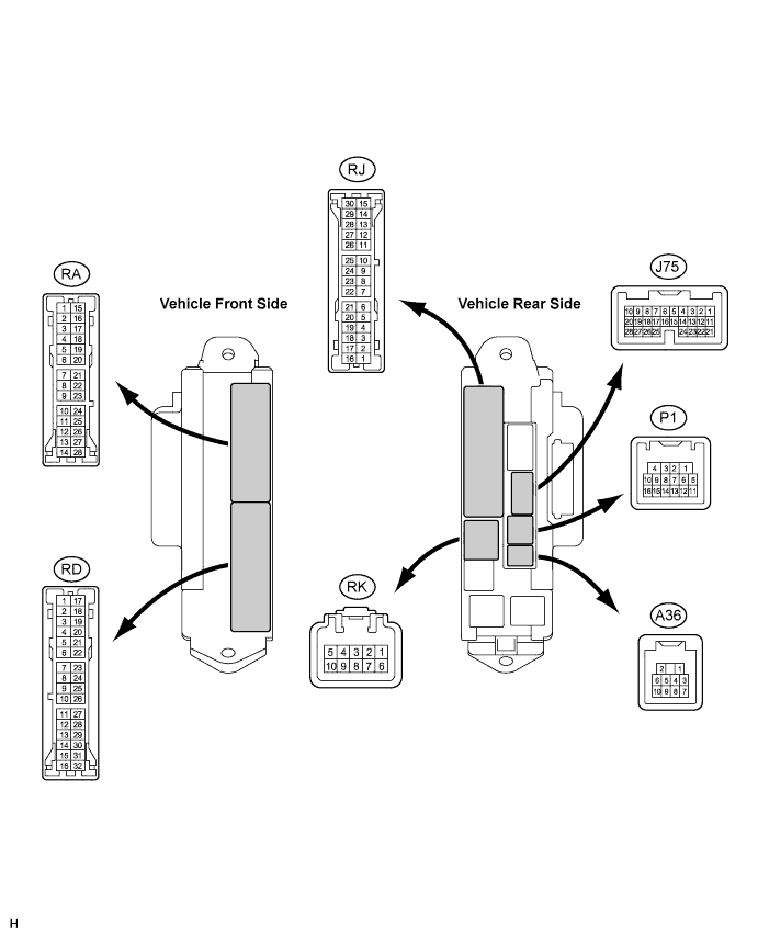

Disconnect the P1, J75, RA, RD, RJ, and RK J/B connectors.
Measure the voltage and resistance according to the value(s) in the table below.
*1: LHD ModelsSymbols (Terminal No.)
Wiring Color
Terminal Description
Condition
Specified Condition
DCTY (P1-14) - Body ground
W - Body ground
Driver door courtesy switch
Driver door CLOSED → OPEN
10 kΩ or higher →
Below 1 Ω
RCTY (P1-16) - Body ground
O - Body ground
Rear right door courtesy switch input
Rear right door CLOSED → OPEN
10 kΩ or higher →
Below 1 Ω
PCTY (J75-23) - Body ground
B (*1), V (*2) - Body ground
Passenger door courtesy switch input
Passenger door CLOSED → OPEN
10 kΩ or higher →
Below 1 Ω
LCTY (RA-11) - Body ground
BR - Body ground
Rear left door courtesy switch input
Rear left door CLOSED → OPEN
10 kΩ or higher →
Below 1 Ω
GND2 (RD-7) - Body ground
W-B - Body ground
Ground
Always
Below 1 Ω
IG (RD-14) - Body ground
B - Body ground
Engine power supply
Engine switch on (IG) → off
10 to 14 V →
Below 1 V
GND1 (RD-17) - Body ground
W-B - Body ground
Ground
Always
Below 1 Ω
ACC (RD-27) - Body ground
O - Body ground
ACC power supply
Engine switch on (ACC) → off
10 to 14 V →
Below 1 V
L1 (RJ-7) - Body ground
BR - Body ground
Passenger door control switch LOCK input
Passenger door control switch OFF → LOCK
10 kΩ or higher →
Below 1 Ω
UL1 (RJ-10) - Body ground
B - Body ground
Passenger door control switch UNLOCK input
Passenger door control switch OFF → UNLOCK
10 kΩ or higher →
Below 1 Ω
BECU (RK-5) - Body ground
G-R - Body ground
+B (BECU) power supply
Always
10 to 14 V
*2: RHD Models
If the result is not as specified, there may be a malfunction on the wire harness side.Reconnect the J/B connectors.
Measure the voltage according to the value(s) in the table below.
If the result is not as specified, the main body ECU RH (cowl side J/B RH) may have a malfunction.Symbols (Terminal No.)
Wiring Color
Terminal Description
Condition
Specified Condition
LSWL (RA-2) - Body ground
R - Body ground
Rear left door lock position switch input
Rear left door UNLOCK → LOCK
Below 1 V →
10 to 14 V (or pulse generation)
GSW (RA-7) - GND
L - Body ground
Center airbag sensor signal
Engine switch on (IG)
4.5 to 5.5 V
ACTD (P1-4) - Body ground
L (*1), LG (*2) - Body ground
Door lock motor UNLOCK drive output (Driver door)
Door control switch (Master switch or passenger side switch) or driver side door key cylinder OFF → UNLOCK → OFF
Below 1 V →
10 to 14 V →
Below 1 V
ACT+ (RJ-9) - Body ground
L - Body ground
Door lock motor LOCK drive output (All doors)
Door control switch (Master switch or passenger side switch) or driver side door key cylinder OFF → LOCK → OFF
Below 1 V →
10 to 14 V →
Below 1 V
ACT- (RJ-17) - Body ground
LG - Body ground
Door lock motor UNLOCK drive output (All doors)
Door control switch (Master switch or passenger side switch) or driver side door key cylinder OFF → UNLOCK → OFF
Below 1 V →
10 to 14 V →
Below 1 V
LSWR (J75-5) - Body ground
V - Body ground
Rear right door lock position switch input
Rear right door UNLOCK → LOCK
Below 1 V →
10 to 14 V (or pulse generation)
LSWP (J75-27) - Body ground
W - Body ground
Passenger door lock position switch input
Passenger door UNLOCK → LOCK
Below 1 V →
10 to 14 V (or pulse generation)
| CHECK MULTIPLEX NETWORK MASTER SWITCH ASSEMBLY |

Disconnect the M7 switch connector.
Measure the voltage and resistance according to the value(s) in the table below.
If the result is not as specified, there may be a malfunction on the wire harness side.Symbols (Terminal No.)
Wiring Color
Terminal Description
Condition
Specified Condition
CPUB (M7-9) - GND (M7-2)
G - W-B
Battery power supply
Always
10 to 14 V
BDR (M7-10) - GND (M7-2)
L - W-B
Battery power supply
Always
10 to 14 V
SIG (M7-20) - GND (M7-2)
B - W-B
SIG power supply
Engine switch on (IG) → off
10 to 14 V →
Below 1 V
GND (M7-2) - Body ground
W-B - Body ground
Ground
Always
Below 1 Ω
KL (M7-4) - GND (M7-2)
L - W-B
Door key-linked door lock input
Using key, operate driver door lock cylinder to LOCK → UNLOCK
Below 1 Ω →
10 kΩ or higher
KUL (M7-14) - GND (M7-2)
W - W-B
Door key-linked door unlock input
Using key, operate driver door lock cylinder to LOCK → UNLOCK
Below 1 Ω →
10 kΩ or higher
LSW (M7-16) - GND (M7-2)
SB - W-B
Driver side door lock position switch input
Driver side door is unlocked → locked
Below 1 Ω →
10 kΩ or higher
| CHECK DOUBLE DOOR LOCK ECU |

Disconnect the P34 ECU connector.
Measure the voltage and resistance according to the value(s) in the table below.
If the result is not as specified, there may be a malfunction on the wire harness side.Symbols (Terminal No.)
Wiring Color
Terminal Description
Condition
Specified Condition
+B (P34-1) - Body ground
R - Body ground
Battery power supply
Always
10 to 14 V
CPUB (P34-7) - Body ground
LG - Body ground
Battery power supply
Always
10 to 14 V
GND (P34-14) - Body ground
W-B - Body ground
Ground
Always
Below 1 Ω
MPX1 (P34-9) - Body ground
LG - Body ground
BEAN signal input/output
Always
10 kΩ or higher
Reconnect the P34 ECU connector.
Measure the voltage according to the value(s) in the table below.
If the result is not as specified, the ECU may have a malfunction.Symbols (Terminal No.)
Wiring Color
Terminal Description
Condition
Specified Condition
DLPD (P34-5) - Body ground
SB - Body ground
Front RH double lock position switch input
Double lock UNSET → SET
5 V or higher → Below 1 V
DLPP (P34-6) - Body ground
GR - Body ground
Front LH double lock position switch input
Double lock UNSET → SET
5 V or higher → Below 1 V
DLPR (P34-11) - Body ground
L - Body ground
Rear RH double lock position switch input
Double lock UNSET → SET
5 V or higher → Below 1 V
DLPL (P34-12) - Body ground
Y - Body ground
Rear LH double lock position switch input
Double lock UNSET → SET
5 V or higher → Below 1 V
ACTS (P34-3) - Body ground
V - Body ground
All door double lock motor set on output
Double lock UNSET → SET
Below 1 V → 10 to 14 V
ACTR (P34-4) - Body ground
P - Body ground
All door double lock motor set off output
Double lock SET → UNSET
Below 1 V → 10 to 14 V