Turn Signal Light Circuit
Circuit diagnosis
DESCRIPTION
The main body ECU LH controls the operation of the turn signal flasher. The turn signal flasher blinks the turn signal lights.The main body ECU LH receives RH/LH turn signal light blink request signals from the combination switch ECU through BEAN communication and sends operation signals to the turn signal flasher.
WIRING DIAGRAM
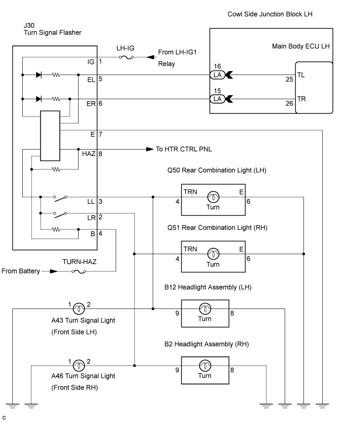

INSPECTION PROCEDURE
| 1. CHECK TURN SIGNAL LIGHT (OPERATION) |

Turn the engine switch on (IG).
When the turn signal light switch is operated, check that the corresponding turn signal lights flash.
- HINT:
- The front, side and rear turn signal lights share the same drive circuit. Therefore, if either the front or rear turn signal lights do not come on, there may be a problem in the circuit between the turn signal flasher and the bulb, or the circuit between the bulb and body ground.
- Result:
Result
Proceed to
Neither left nor right turn signal lights flash
A
Left turn signal lights do not flash
B
Right turn signal lights do not flash
C
|
|
||||
|
|
||||

| A | |
 |
| 2. PERFORM ACTIVE TEST BY INTELLIGENT TESTER |
Connect the intelligent tester to the DLC3.
Turn the engine switch on (IG).
Turn the intelligent tester on.
Select the item(s) in the ACTIVE TEST, and check the operation.
ACTIVE TEST: Body No. 3 (Main body ECU LH) Item
Test Details
Diagnostic Note
Turn Lamp RH
RH side turn signal lights operation ON / OFF
-
Turn Lamp LH
LH side turn signal lights operation ON / OFF
-
- OK:
- Turn signal lights flash.
|
|
||||
| OK | ||
 |
||
| ||
| 3. INSPECT FUSE (LH-IG, TURN-HAZ) |
Remove the LH-IG fuse from the cowl side J/B LH.
Remove the TURN-HAZ fuse from the engine room No. 1 J/B.
Measure the resistance of the fuses.
- Standard resistance:
- Below 1 Ω
|
|
||||

| OK | |
|
| 4. CHECK HARNESS AND CONNECTOR (POWER SOURCE) |
Disconnect the J30 flasher connector.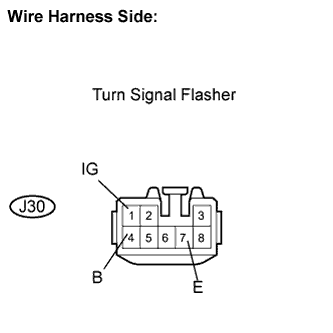
Measure the resistance according to the value(s) in the table below.
- Standard resistance:
Tester Connection
Condition
Specified Condition
J30-7 (E) - Body ground
Always
Below 1 Ω
Measure the voltage according to the value(s) in the table below.
- Standard voltage:
Tester Connection
Condition
Specified Condition
J30-4 (B) - Body ground
Always
10 to 14 V
J30-1 (IG) - Body ground
Engine switch on (IG)
10 to 14 V
|
|
||||
| OK | |
|
| 5. REPLACE TURN SIGNAL FLASHER |
Temporarily replace the turn signal flasher with a new or normally functioning one.
Check that the turn signal lights flash.
- OK:
- Turn signal lights flash.
|
|
||||
| OK | ||
|
||
| ||
| 6. PERFORM ACTIVE TEST BY INTELLIGENT TESTER |
Connect the intelligent tester to the DLC3.
Turn the engine switch on (IG).
Turn the intelligent tester on.
Select the item(s) in the ACTIVE TEST, and check the operation.
ACTIVE TEST: Body No. 3 (Main body ECU LH) Item
Test Details
Diagnostic Note
Turn Lamp LH
LH side turn signal lights operation ON / OFF
-
- OK:
- Turn signal lights flash.
|
|
||||
| OK | ||
|
||
| ||
| 7. CHECK HARNESS AND CONNECTOR (MAIN BODY ECU LH - BODY GROUND) |
Disconnect the LA main body ECU LH connector.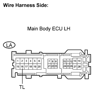
Measure the voltage according to the value(s) in the table below.
- Standard voltage:
Tester Connection
Condition
Specified Condition
LA-16 (TL) - Body ground
Always
10 to 14 V
|
|
||||
| OK | |
|
| 8. CHECK HARNESS AND CONNECTOR (TURN SIGNAL FLASHER - HEADLIGHT) |
Disconnect the J30 flasher connector.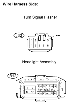
Disconnect the B12 headlight connector.
Measure the resistance according to the value(s) in the table below.
- Standard resistance:
Tester Connection
Condition
Specified Condition
J30-3 (LL) - B12-9
Always
Below 1 Ω
J30-3 (LL) - Body ground
Always
10 kΩ or higher
|
|
||||
| OK | |
|
| 9. REPLACE TURN SIGNAL FLASHER |
Temporarily replace the turn signal flasher with a new or normally functioning one.
Check that the turn signal lights flash.
- OK:
- Turn signal lights flash.
|
|
||||
| OK | ||
|
||
| ||
| 10. CHECK HARNESS AND CONNECTOR (MAIN BODY ECU LH - TURN SIGNAL FLASHER) |
Disconnect the LA main body ECU LH connector.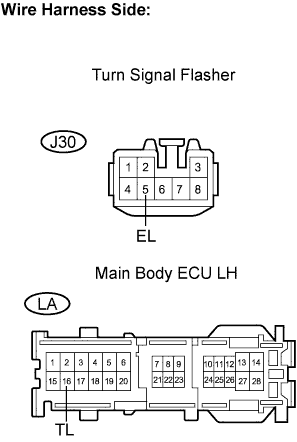
Disconnect the J30 flasher connector.
Measure the resistance according to the value(s) in the table below.
- Standard resistance:
Tester Connection
Condition
Specified Condition
LA-16 (TL) - J30-5 (EL)
Always
Below 1 Ω
LA-16 (TL) - Body ground
Always
10 kΩ or higher
|
|
||||
| OK | ||
|
||
| ||
| 11. PERFORM ACTIVE TEST BY INTELLIGENT TESTER |
Connect the intelligent tester to the DLC3.
Turn the engine switch on (IG).
Turn the intelligent tester on.
Select the item(s) in the ACTIVE TEST, and check the operation.
ACTIVE TEST: Body No. 3 (Main body ECU LH) Item
Test Details
Diagnostic Note
Turn Lamp RH
RH side turn signal lights operation ON / OFF
-
- OK:
- Turn signal lights flash.
|
|
||||
| OK | ||
|
||
| ||
| 12. CHECK HARNESS AND CONNECTOR (MAIN BODY ECU LH - BODY GROUND) |
Disconnect the LA main body ECU LH connector.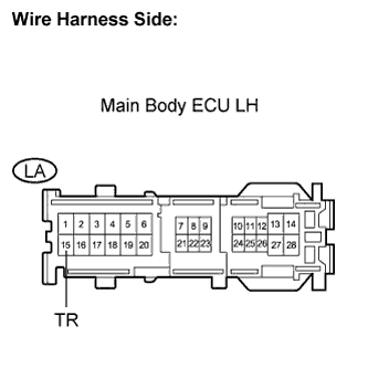
Measure the voltage according to the value(s) in the table below.
- Standard voltage:
Tester Connection
Condition
Specified Condition
LA-15 (TR) - Body ground
Always
10 to 14 V
|
|
||||
| OK | |
|
| 13. CHECK HARNESS AND CONNECTOR (TURN SIGNAL FLASHER - HEADLIGHT) |
Disconnect the J30 flasher connector.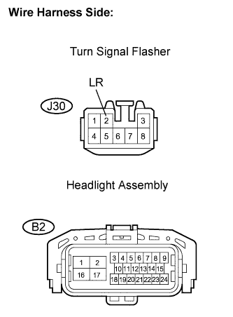
Disconnect the B2 headlight connector.
Measure the resistance according to the value(s) in the table below.
- Standard resistance:
Tester Connection
Condition
Specified Condition
J30-2 (LR) - B2-9
Always
Below 1 Ω
J30-2 (LR) - Body ground
Always
10 kΩ or higher
|
|
||||
| OK | |
|
| 14. REPLACE TURN SIGNAL FLASHER |
Temporarily replace the turn signal flasher with a new or normally functioning one.
Check that the turn signal lights flash.
- OK:
- Turn signal lights flash.
|
|
||||
| OK | ||
|
||
| ||
| 15. CHECK HARNESS AND CONNECTOR (MAIN BODY ECU LH - TURN SIGNAL FLASHER) |
Disconnect the LA main body ECU LH connector.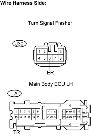
Disconnect the J30 flasher connector.
Measure the resistance according to the value(s) in the table below.
- Standard resistance:
Tester Connection
Condition
Specified Condition
LA-15 (TR) - J30-6 (ER)
Always
Below 1 Ω
LA-15 (TR) - Body ground
Always
10 kΩ or higher
|
|
||||
| OK | ||
|
||
| ||