P0100
Diagnostic trouble codes
DESCRIPTION
The Mass Air Flow (MAF) meter is a sensor that measures the amount of air flowing through the valve.The ECM uses this information to determine the fuel injection time and to prove appropriate air-fuel ratio.
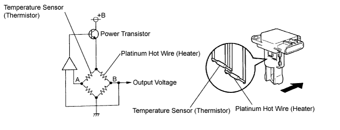
Inside the MAF meter, there is a heated platinum wire which is exposed to the flow of intake air.
By applying a specific electrical current to the wire, the ECM heats it to a given temperature. The flow of incoming air cools both the wire and an internal thermistor, affecting their resistance. To maintain a constant current value, the ECM varies the voltage applied to these components in the MAF meter. The voltage level is proportional to the airflow through the sensor, and the ECM uses it to calculate the intake air volume.
The circuit is constructed so that the platinum hot wire and the temperature sensor provide a bridge circuit, and the power transistor is controlled so that the potentials of A and B remain equal to maintain the predetermined temperature.
- HINT:
- When any of these DTCs are set, the ECM enters fail-safe mode. During fail-safe mode, the ignition timing is calculated by the ECM, according to the engine RPM and throttle valve position. Fail-safe mode continues until a pass condition is detected.

| DTC No. |
DTC Detection Condition |
Trouble Area |
| P0100 |
Open or short in Mass Air Flow (MAF) meter circuit for 3 seconds |
|
| P0102 |
Open in Mass Air Flow (MAF) meter circuit for 3 seconds |
|
| P0103 |
Short in Mass Air Flow (MAF) meter circuit for 3 seconds |
|
- HINT:
- When any of these DTCs are set, check the air-flow rate by entering the following menus on the intelligent tester: Power train / Engine / Data List / MAF.
Mass Air Flow Rate (gm/s)
Malfunctions
Approximately 0.0
- Open in Mass Air Flow (MAF) meter power source circuit
- Open or short in VG circuit
271.0 or more
- Open in EVG circuit
- Open in Mass Air Flow (MAF) meter power source circuit
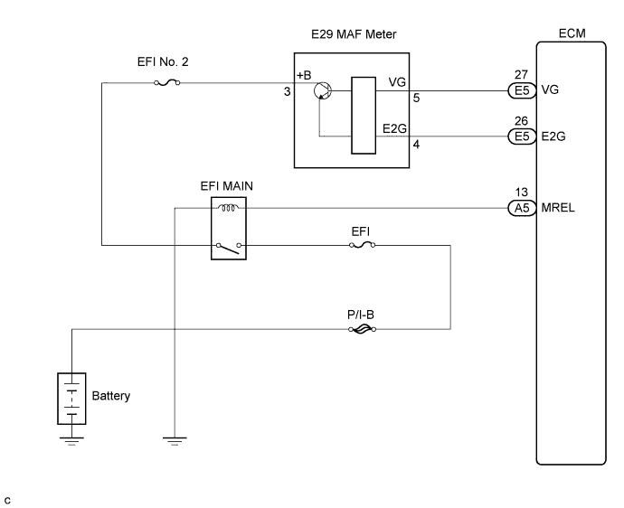
WIRING DIAGRAM
INSPECTION PROCEDURE
- HINT:
- Read freeze frame data using the intelligent tester. Freeze frame data records the engine conditions when malfunctions are detected. When troubleshooting, freeze frame data can help determine if the vehicle was moving or stationary, if the engine was warmed up or not, if the air-fuel ratio was lean or rich, and other data from the time the malfunction occurred (Click here).
| 1. READ VALUE OF MASS AIR FLOW METER (MAF) |

Connect the intelligent tester to the DLC3.
Start the engine.
Turn the tester ON.
Enter the following menus: Power train / Engine / Data List / MAF.
Read the values displayed on the tester.
- Result:
Mass Air Flow Rate (gm/s)
Proceed to
0.0
A
271.0 or more
B
Between 1.0 and 270.0 (*1)
C
|
|
||||
|
|
||||


| A | |
 |
| 2. INSPECT MASS AIR FLOW METER (POWER SOURCE VOLTAGE) |
Disconnect the E29 Mass Air Flow (MAF) meter connector.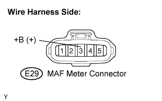
Turn the engine switch on (IG).
Measure the voltage of the wire harness side connector and body ground.
- Standard voltage:
Tester Connection
Specified Condition
+B (E29-3) - Body ground
9 to 14 V
Reconnect the MAF meter connector.
|
|
||||
| OK | |
|
| 3. INSPECT ECM (VG VOLTAGE) |
Start the engine.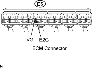
Measure the voltage of the E5 ECM connector.
- HINT:
- The transmission gear selector lever should be in the P or N position and the A/C switch should be turned OFF.
- Standard voltage:
Tester Connection
Condition
Specified Condition
VG (E5-27) - E2G (E5-26)
Engine idling
0.5 to 3.0 V
|
|
||||
| NG | |
|
| 4. CHECK HARNESS AND CONNECTOR (MASS AIR FLOW METER - ECM) |
Disconnect the E29 MAF meter connector.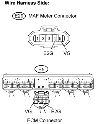
Disconnect the E5 ECM connector.
Measure the resistance of the wire harness side connector.
- Standard resistance (Check for open):
Tester Connection
Specified Condition
VG (E29-5) - VG (E5-27)
Below 1 Ω
E2G (E29-4) - E2G (E5-26)
Below 1 Ω
- Standard resistance (Check for short):
Tester Connection
Specified Condition
VG (E29-5) or VG (E5-27) - Body ground
10 kΩ or higher
Reconnect the MAF meter connector.
Reconnect the ECM connector.
|
|
||||
| OK | ||
 |
||
| ||
| 5. CHECK HARNESS AND CONNECTOR (MASS AIR FLOW METER - INTEGRATION RELAY) |
Inspect the EFI No. 2 fuse.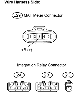
Remove the EFI No. 2 fuse from the engine room No.2 relay block.
Check the EFI No. 2 fuse resistance.
- Standard resistance:
- Below 1 Ω
Reinstall the EFI No. 2 fuse.
Disconnect the E29 MAF meter connector.
Remove the integration relay from the engine room J/B and R/B No. 2.
Measure the resistance of the wire harness side connector.
- Standard resistance (Check for open):
Tester Connection
Specified Condition
+B (E29-3) - 2A-8
Below 1 Ω
- Standard resistance (Check for short):
Tester Connection
Specified Condition
+B (E29-3) or 2A-8 - Body ground
10 kΩ or higher
Reconnect the MAF meter connector.
Reinstall the integration relay.
|
|
||||
| OK | ||
|
||
| ||
| 6. INSPECT ECM (SENSOR GROUND) |
Measure the resistance of the ECM connector.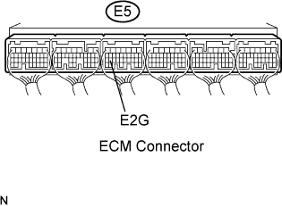
- Standard resistance:
Tester Connection
Specified Condition
E2G (E5-26) - Body ground
Below 1 Ω
|
|
||||
| OK | |
|
| 7. CHECK HARNESS AND CONNECTOR (MASS AIR FLOW METER - ECM) |
Disconnect the E29 MAF meter connector.
Disconnect the E5 ECM connector.
Measure the resistance of the wire harness side connector.
- Standard resistance (Check for open):
Tester Connection
Specified Condition
VG (E29-5) - VG (E5-27)
Below 1 Ω
E2G (E29-4) - E2G (E5-26)
Below 1 Ω
- Standard resistance (Check for short):
Tester Connection
Specified Condition
VG (E29-5) or VG (E5-27) - Body ground
10 kΩ or higher
Reconnect the MAF meter connector.
Reconnect the ECM connector.
|
|
||||
| OK | ||
|
||
| ||