INSTALLATION
Removal / installation
| 1. INSTALL CENTER AIRBAG SENSOR ASSEMBLY |

Check that the engine switch is off.
Check that the battery negative (-) terminal is disconnected.
- NOTICE:
- After disconnecting the negative battery terminal, wait for at least 90 seconds before starting the operation.
Install the center airbag sensor assembly with the nut and 2 bolts.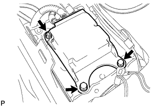

- Torque:
- 17.5 N*m{ 179 kgf*cm , 13 ft.*lbf }
- NOTICE:
- If the center airbag sensor assembly has been dropped, or there are any cracks, dents or other defects in the case, bracket or connector, replace it with a new one.
- When installing the center airbag sensor assembly, be careful that the SRS wiring does not interfere with other parts and that it is not pinched between other parts.
- If the center airbag sensor assembly has been dropped, or there are any cracks, dents or other defects in the case, bracket or connector, replace it with a new one.
Check that there is no looseness in the installation parts of the center airbag sensor assembly.
Connect the holder (with connectors).
Check that the water-proof sheet is properly set.
| 2. INSTALL CONSOLE BOX |
Engage the 2 claws and 2 clips.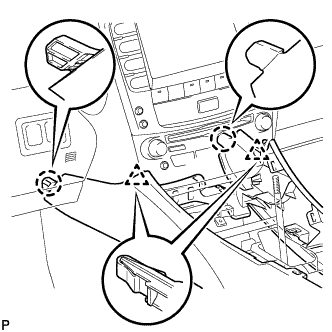
Install the 2 bolts <C>.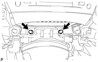
Install the 2 bolts <C>.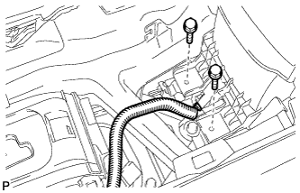
Connect the connector.
Connect the connectors.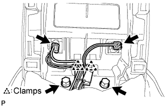
Engage the 2 clamps.
Install the 2 bolts <C>.
| 3. INSTALL CONSOLE BOX REGISTER ASSEMBLY |
Engage the 2 claws and 4 clips, and then install the console box register assembly.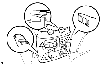
Install the rear ash receptacle assembly.
| 4. INSTALL REAR ASH RECEPTACLE ASSEMBLY |
| 5. INSTALL FRONT ASH RECEPTACLE SUB-ASSEMBLY |
Engage the 6 clips.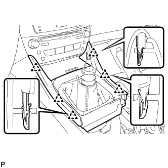
Close the snap.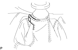
| 6. INSTALL FRONT CONSOLE PANEL SUB-ASSEMBLY (for Manual Transmission) |
Engage the 6 clips.
Close the snap.
| 7. INSTALL REAR CONSOLE PANEL SUB-ASSEMBLY (for Manual Transmission) |
Engage the 7 claws and 2 clips.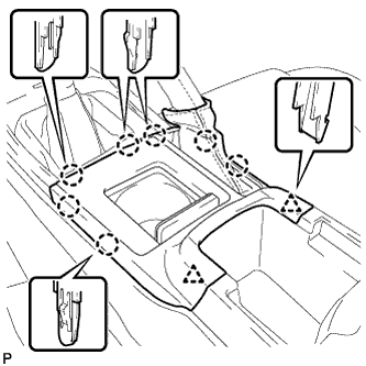
Close the snap.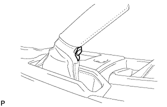
| 8. INSTALL CONSOLE PANEL SUB-ASSEMBLY (for Automatic Transmission) |
Connect the connectors.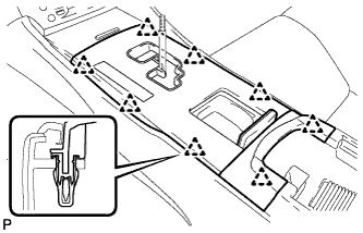
Engage the 8 clips and install the console panel sub-assembly.
| 9. INSTALL UPPER NO. 2 CONSOLE PANEL GARNISH (for Automatic Transmission) |
Engage the claw and 2 clips, and then install the upper No. 2 console panel garnish.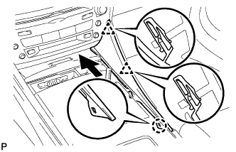
| 10. INSTALL UPPER NO. 1 CONSOLE PANEL GARNISH (for Automatic Transmission) |
Engage the claw and 2 clips, and then install the upper No. 1 console panel garnish.
| 11. INSTALL SHIFT LEVER KNOB SUB-ASSEMBLY (for Manual Transmission) |
| 12. INSTALL SHIFT LEVER KNOB SUB-ASSEMBLY (for Automatic Transmission) |
| 13. CONNECT CABLE TO NEGATIVE BATTERY TERMINAL |
| 14. PERFORM INITIALIZATION |
Perform initialization (Click here).
- HINT:
- Some systems need initialization after reconnecting the cable to the negative battery terminal.
| 15. INSPECT SRS WARNING LIGHT |
Inspect the SRS warning light (Click here).