TERMINALS OF ECU
System information
| CHECK SLIDING ROOF DRIVE GEAR SUB-ASSEMBLY (SLIDING ROOF ECU) |


Disconnect the R6 ECU connector.
Measure the resistance and voltage of the wire harness side connector.
Symbols (Terminal No.)
Wiring Color
Terminal Description
Condition
Specified Condition
B (R6-5) - E (R6-7)
L - W-B
+B Power supply
Always
10 to 14 V
IG (R6-6) - E (R6-7)
V - W-B
Engine switch power supply
Engine switch off
Below 1 V
IG (R6-6) - E (R6-7)
V - W-B
Engine switch power supply
Engine switch on (IG)
10 to 14 V
E (R6-7) - Body ground
W-B - Body ground
Ground
Always
Below 1 Ω
Reconnect the R6 ECU connector.
Measure the voltage of the connector.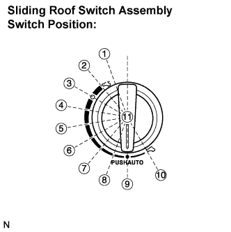
Switch Position
Sliding Roof Position
1
Over stroke position
2
Slide fully open position (Comfort stop position)
3
Slide stop position [1]
4
Slide stop position [2]
5
Slide stop position [3]
6
Slide stop position [4]
7
Slide stop position [5]
8
Slide stop position [6]
9
Slide fully close position
10
Tilt fully open position
11
Auto fully closed, comfort stop position
If the result is not as specified, the ECU may have a malfunction.Symbols (Terminal No.)
Wiring Color
Terminal Description
Condition
Specified Condition
CHK (R6-2) - E (R6-7)
LG - W-B
Sliding roof motor auto operation
Engine switch on (IG), sliding roof switch pushed.
10 to 14 V
OPN (R6-9) - E (R6-7)
B - W-B
Sliding roof motor open
Engine switch off, sliding roof switch position [1], [2], [3]
Below 1 V
OPN (R6-9) - E (R6-7)
B - W-B
Sliding roof motor open
Engine switch on (IG), sliding roof switch position [1], [2], [3]
10 to 14 V
CLS (R6-8) - E (R6-7)
SB - W-B
Sliding roof motor close
Engine switch off, sliding roof switch position [5], [6], [9], [10]
Below 1 V
CLS (R6-8) - E (R6-7)
SB - W-B
Sliding roof motor close
Engine switch on (IG), sliding roof switch position [5], [6], [9], [10]
10 to 14 V
UP (R6-3) - E (R6-7)
O - W-B
Sliding roof motor up
Engine switch off, sliding roof switch position [2], [3], [4], [5], [6], [7]
Below 1 V
UP (R6-3) - E (R6-7)
O - W-B
Sliding roof motor up
Engine switch on (IG), sliding roof switch position [2], [3], [4], [5], [6], [7]
10 to 14 V
DWN (R6-4) - E (R6-7)
Y - W-B
Sliding roof motor down
Engine switch off, sliding roof switch position [1], [2], [6], [7], [8], [9]
Below 1 V
DWN (R6-4) - E (R6-7)
Y - W-B
Sliding roof motor down
Engine switch on (IG), sliding roof switch position [1], [2], [6], [7], [8], [9]
10 to 14 V