REMOVAL
Removal / installation
| 1. PRECAUTION |

- HINT:
- (Click here)
| 2. REMOVE COOL AIR INTAKE DUCT SEAL |
Remove the 11 clips and intake duct seal.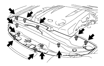

| 3. REMOVE ENGINE ROOM SIDE COVER LH |
Remove the 2 clips and side cover.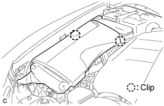
| 4. REMOVE ENGINE ROOM SIDE COVER RH |
Remove the 2 clips and side cover.
| 5. REMOVE FRONT UPPER FENDER PROTECTOR LH |
Using a clip remover, separate the clip on the rubber portion of the cowl top ventilator louver sub-assembly from the front upper fender protector LH.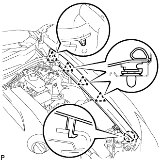
Disengage the 3 clips and the claw to remove the front fender protector upper LH.
| 6. REMOVE FRONT UPPER FENDER PROTECTOR RH |
- HINT:
- Use the same procedures for the RH side and the LH side.
| 7. REMOVE ROOF DRIP SIDE FINISH MOULDING LH |
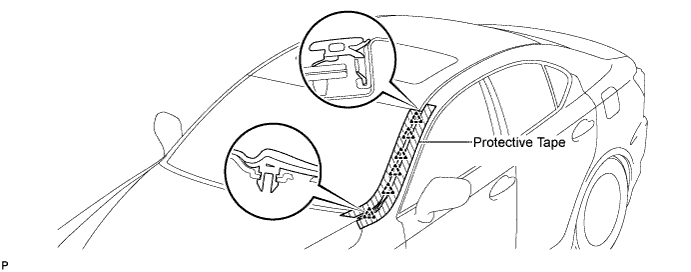
Put protective tape around the roof drip side finish moulding.
Using a moulding remover, disengage the 6 clips and remove the roof drip side finish moulding.
- NOTICE:
- Do not remove the clips.
- If the clips are damaged or fall off, replace them with new clips.
- Do not remove the clips.
| 8. REMOVE ROOF DRIP SIDE FINISH MOULDING RH |
- HINT:
- Use the same procedures for the RH side and the LH side.
| 9. REMOVE FRONT WIPER ARM HEAD CAP |
Using a screwdriver, remove the front wiper arm head cap.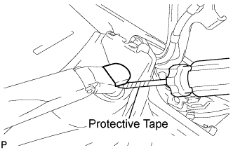
- HINT:
- Use the same procedures for the RH side and the LH side.
- Tape the screwdriver tip before use.
- Use the same procedures for the RH side and the LH side.
| 10. REMOVE WINDSHIELD WIPER ARM AND BLADE ASSEMBLY LH |
Remove the nut and the front wiper arm and blade assembly LH.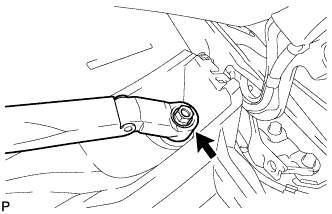
| 11. REMOVE WINDSHIELD WIPER ARM AND BLADE ASSEMBLY RH |
Remove the nut and the front wiper arm and blade assembly RH.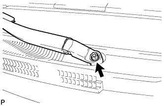
| 12. REMOVE COWL TOP VENTILATOR LOUVER SUB-ASSEMBLY |
Remove the 2 clips.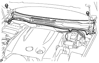
Disengage the 11 claws, and pull out the cowl top ventilator louver sub-assembly.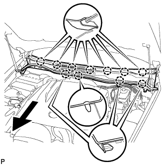
| 13. DRAIN BRAKE FLUID |
- NOTICE:
- If brake fluid leaks onto any painted surface, wash off or remove the brake fluid completely.
| 14. REMOVE NO. 3 ENGINE ROOM RELAY BLOCK |
Remove the bolt, nut and No. 3 engine room relay block.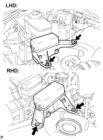
- NOTICE:
- Cover the No. 3 engine room relay block with a shop rag or a piece of cloth to prevent brake fluid from getting on it.
| 15. SEPARATE CLUTCH RESERVOIR HOSE (for Manual Transmission) |
Remove the clip and separate the clutch reservoir hose.
| 16. REMOVE BRAKE MASTER CYLINDER SUB-ASSEMBLY |
Disengage the clamp and disconnect the warning switch connector.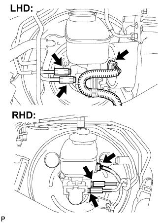
Using SST, disconnect the 2 brake lines from the brake master cylinder sub-assembly.
- SST
- 09023-00101
Remove the 2 nuts and separate the brake actuator assembly.
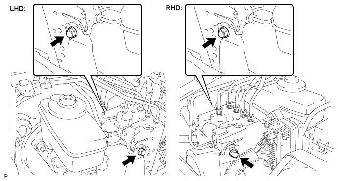
Remove the 2 nuts and brake master cylinder sub-assembly from the brake booster assembly.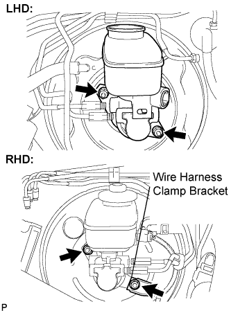
Remove the O-ring from the brake master cylinder sub-assembly.