INSTALLATION
Removal / installation
| 1. INSTALL STARTER ASSEMBLY |

Install the starter with the 2 bolts.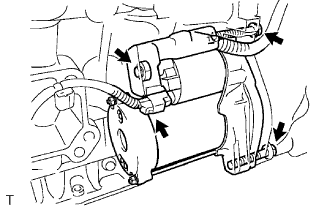

- Torque:
- 58 N*m{ 591 kgf*cm , 43 ft.*lbf }
Connect the wire harness to terminal 30 and install the nut, and then attach the terminal cap.
- Torque:
- 9.8 N*m{ 100 kgf*cm , 87 in.*lbf }
Connect the terminal 50 connector to the starter assembly.
| 2. INSTALL EXHAUST MANIFOLD SUB-ASSEMBLY LH |
Install a new gasket and the exhaust manifold with 6 new nuts.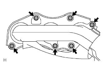
- Torque:
- 21 N*m{ 214 kgf*cm , 15 ft.*lbf }
Connect the air fuel ratio sensor (for sensor 1) connector.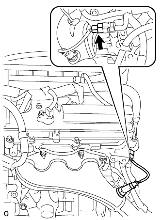
Install the engine wire bracket with the bolt (A).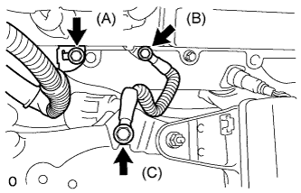
- Torque:
- 10 N*m{ 102 kgf*cm , 7 ft.*lbf }
Install the ground cable with the 2 bolts (B, C).
- Torque:
- Bolt (B):
- 10 N*m{ 102 kgf*cm , 7 ft.*lbf }
- Bolt (C):
- 13 N*m{ 133 kgf*cm , 10 ft.*lbf }
| 3. INSTALL ENGINE ROOM NO. 3 RELAY BLOCK (for LHD) |
Install the engine room No. 3 relay block with the bolt and nut.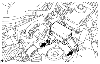
- Torque:
- 12.5 N*m{ 127 kgf*cm , 9 ft.*lbf }
| 4. INSTALL ENGINE ROOM RELAY BLOCK ASSEMBLY (for RHD) |
| 5. REMOVE NO. 4 ENGINE WIRE (for RHD) |
| 6. INSTALL NO. 1 RELAY BLOCK COVER (for RHD) |
| 7. INSTALL BATTERY TRAY (for RHD) |
Install the battery tray with the 2 bolts.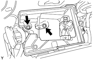
- Torque:
- 5.0 N*m{ 51 kgf*cm , 44 in.*lbf }
| 8. INSTALL POWER STEERING ECU ASSEMBLY (for RHD) |
Connect connector (c) to the power steering ECU assembly.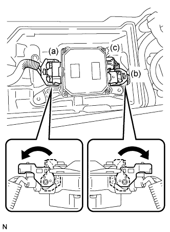
Connect 2 power steering ECU assembly connectors (a) and (b) and securely lock the connectors.
Install the power steering ECU assembly to the battery tray with the 3 bolts.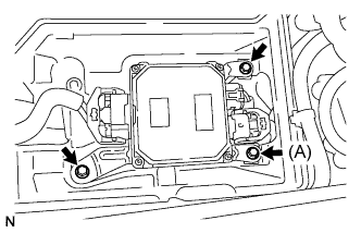
- Torque:
- 5.0 N*m{ 51 kgf*cm , 44 in.*lbf }
Install the No. 1 battery tray support.
| 9. INSTALL BATTERY (for RHD) |
Install the battery.
Install the battery insulator.
Install the battery clamp with the 2 nuts.
- Torque:
- 2.9 N*m{ 30 kgf*cm , 26 in.*lbf }
Connect the positive (+) battery cable to the battery.
- Torque:
- 5.6 N*m{ 57 kgf*cm , 50 in.*lbf }
Connect the negative (-) battery cable to the battery.
- Torque:
- 5.6 N*m{ 57 kgf*cm , 50 in.*lbf }
| 10. INSTALL NO. 1 EXHAUST PIPE SUPPORT BRACKET SUB-ASSEMBLY (for Automatic Transmission) |
Install the exhaust pipe No. 1 support bracket sub-assembly with the 2 bolts.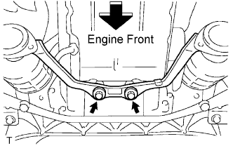
- Torque:
- 43 N*m{ 438 kgf*cm , 32 ft.*lbf }
| 11. INSTALL FRONT EXHAUST PIPE ASSEMBLY |
Using a vernier caliper, measure the free length of the compression springs.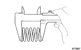
- Minimum length:
- 38.5 mm (1.516 in.)
Install a new gasket to the rear end of the front exhaust pipe.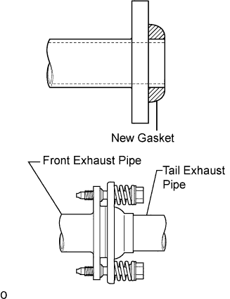
- NOTICE:
- Be careful with the installation direction of the gasket.
- Be careful with the installation direction of the gasket.
- Do not reuse the gasket.
- Do not reuse the gasket.
- To ensure a proper seal, do not use the tail exhaust pipe to force the gasket onto the front exhaust pipe.
- HINT:
- Using a plastic hammer, uniformly strike the gasket so that the gasket and front exhaust pipe are properly fit.
- To ensure a proper seal, do not use the tail exhaust pipe to force the gasket onto the front exhaust pipe.
Install 3 new gaskets and front exhaust pipe assembly.
- CAUTION:
- Do not reuse the gaskets.
Install the 2 bolts and 2 compression springs.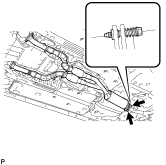
- Torque:
- 43 N*m{ 438 kgf*cm , 32 ft.*lbf }
Install 4 new nuts and 4 bolts.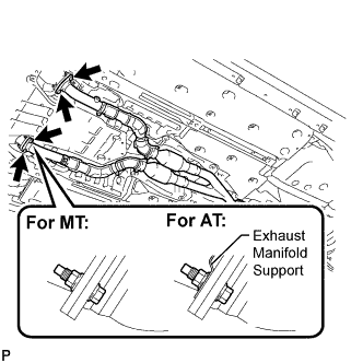
- Torque:
- 62 N*m{ 632 kgf*cm , 46 ft.*lbf }
- NOTICE:
- Do not reuse the nuts.
| 12. INSTALL HEATED OXYGEN SENSOR |
Before installing the heated oxygen sensors, twist the sensor wires counterclockwise 4 turns.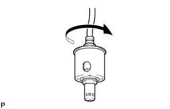
Using the SST, install the heated oxygen sensors to the front exhaust pipe.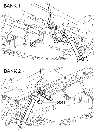
- SST
- 09224-00010
- Torque:
- 44 N*m{ 449 kgf*cm , 33 ft.*lbf }
After installing the sensors, check that the sensor wires are not twisted.
If the sensor wires are twisted, reinstall them.
Install the grommets of the heated oxygen sensors.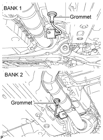
| 13. INSTALL FRONT CENTER FLOOR BRACE |
Install the front center floor brace with the 4 bolts.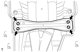
- Torque:
- 7.4 N*m{ 75 kgf*cm , 65 in.*lbf }
| 14. INSTALL REAR NO. 1 FLOOR PANEL BRACE |
Install the rear No. 1 floor panel brace with the 4 bolts.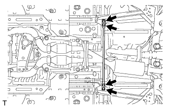
- Torque:
- 19 N*m{ 194 kgf*cm , 14 ft.*lbf }
| 15. INSTALL ENGINE ROOM SIDE COVER LH |
Install the side cover with the 5 clips.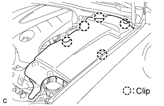
| 16. INSTALL COOL AIR INTAKE DUCT SEAL |
Install the intake duct seal with the 11 clips.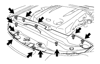
| 17. CONNECT CABLE TO NEGATIVE BATTERY TERMINAL |
- Torque:
- 5.4 N*m{ 55 kgf*cm , 48 in.*lbf }
| 18. CHECK FOR EXHAUST LEAKS |
| 19. PERFORM INITIALIZATION |
Perform initialization procedure (Click here).
- HINT:
- Some vehicle systems require initialization after reconnecting the negative battery cable.