REMOVAL
Removal / installation
| 1. DISCONNECT CABLE FROM NEGATIVE BATTERY TERMINAL |
| 2. REMOVE COOL AIR INTAKE DUCT SEAL |

Remove the 11 clips and intake duct seal.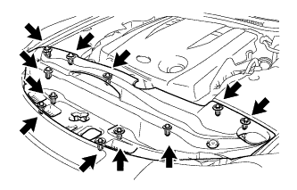

| 3. REMOVE ENGINE ROOM SIDE COVER LH |
Remove the 5 clips and side cover.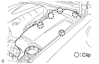
| 4. REMOVE REAR NO. 1 FLOOR PANEL BRACE |
Remove the 4 bolts and rear No. 1 floor panel brace.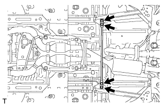
| 5. REMOVE FRONT CENTER FLOOR BRACE |
Remove the 4 bolts and front center floor brace .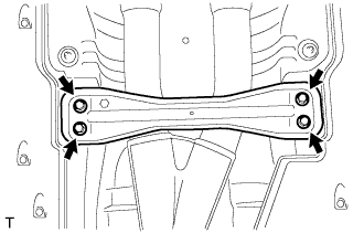
| 6. DISCONNECT HEATED OXYGEN SENSOR |
Remove the grommets of the heated oxygen sensors (BANK 1, BANK 2).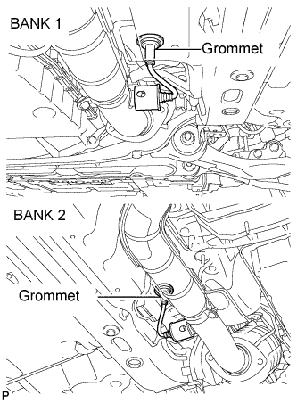
Using the SST, remove a oxygen sensors (BANK 1, BANK 2).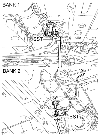
- SST
- 09224-00010
| 7. REMOVE FRONT EXHAUST PIPE ASSEMBLY |
Remove the 4 bolts and 4 nuts.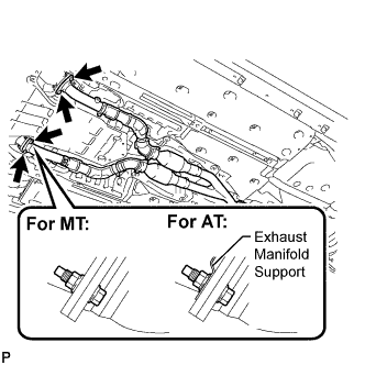
Remove the 2 bolts and 2 compression springs from the tail exhaust pipe assembly.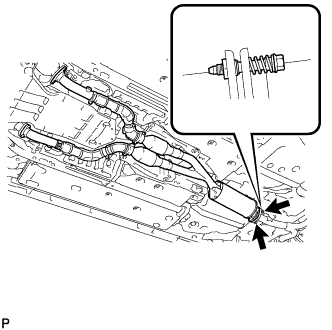
Remove the front exhaust pipe assembly and 3 gaskets.
| 8. REMOVE NO. 1 EXHAUST PIPE SUPPORT BRACKET SUB-ASSEMBLY (for Automatic Transmission) |
Remove the 2 bolts and exhaust pipe No. 1 support bracket sub-assembly.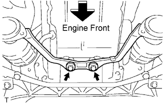
| 9. REMOVE BATTERY (for RHD) |
Disconnect the negative (-) battery cable from the battery.
Disconnect the positive (+) battery cable from the battery.
Remove the 2 nuts and the battery clamp.
Remove the battery insulator.
Remove the battery.
| 10. REMOVE POWER STEERING ECU ASSEMBLY (for RHD) |
Remove the No. 1 battery tray support.
Remove the 3 bolts.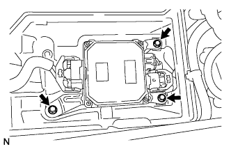
Release the locks of 2 power steering ECU assembly connectors (a) and (b) and disconnect the connectors.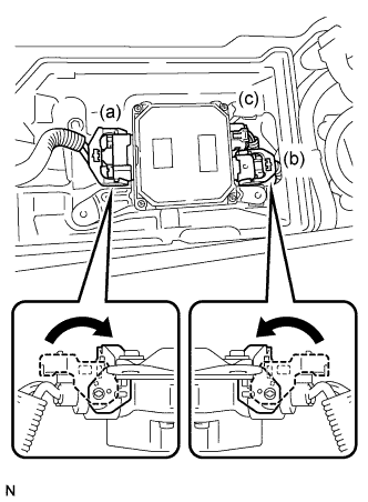
Disconnect connector (c) from the power steering ECU assembly.
Remove the power steering ECU assembly.
| 11. REMOVE BATTERY TRAY (for RHD) |
Remove the 2 bolts and battery tray.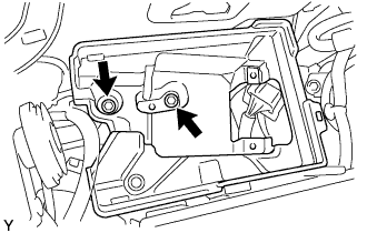
| 12. REMOVE NO. 1 RELAY BLOCK COVER (for RHD) |
| 13. REMOVE NO. 4 ENGINE WIRE (for RHD) |
| 14. REMOVE ENGINE ROOM RELAY BLOCK ASSEMBLY (for RHD) |
Remove the 2 bolts, nut and engine room relay block assembly.
| 15. SEPARATE ENGINE ROOM NO. 3 RELAY BLOCK (for LHD) |
Remove the bolt and nut, and separate the engine room No. 3 relay block.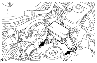
| 16. REMOVE EXHAUST MANIFOLD SUB-ASSEMBLY LH |
Remove the 2 bolts and ground cable.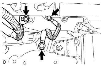
Remove the bolt and engine wire bracket.
Disconnect the air fuel ratio sensor (for sensor 1) connector.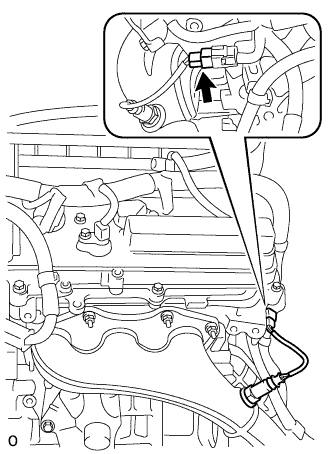
Remove the 6 nuts, exhaust manifold and gasket.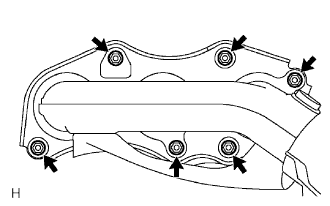
| 17. REMOVE STARTER ASSEMBLY |
Disconnect the terminal 50 connector from the starter assembly.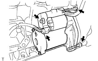
Detach the terminal cap.
Remove the nut and disconnect the wire harness from terminal 30.
Remove the 2 bolts and starter.