TC and CG Terminal Circuit
Circuit diagnosis
DESCRIPTION
Connecting terminals TC and CG of the DLC3 causes the system to enter the self-diagnostic mode. If a malfunction is present, DTCs will be output.- HINT:
- When a particular warning light remains blinking, a ground short in the wiring of terminal TC of the DLC3 or an internal ground short in the relevant ECU is suspected.
WIRING DIAGRAM
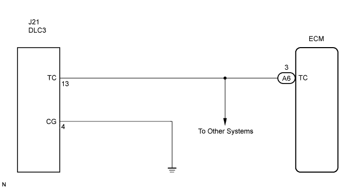

INSPECTION PROCEDURE
| 1. CHECK WIRE HARNESS (TERMINAL TC of DLC3 - ECM) |

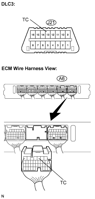 |
Disconnect the A6 connector from the ECM.
Measure the resistance according to the value(s) in the table below.
- Standard resistance:
Tester Connection
Condition
Specified Condition
A6-3 (TC) - J21-13 (TC)
Always
Below 1 Ω
|
|
||||

| OK | |
 |
| 2. CHECK WIRE HARNESS (TERMINAL CG of DLC3 - BODY GROUND) |
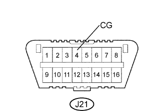 |
Measure the resistance according to the value(s) in the table below.
- Standard resistance:
Tester Connection
Condition
Specified Condition
J21-4 (CG) - Body ground
Always
Below 1 Ω
|
|
||||
| OK | |
|
| 3. CHECK WIRE HARNESS (TERMINALTC of DLC3 - BODY GROUND) |
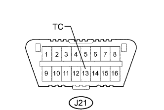 |
Measure the resistance according to the value(s) in the table below.
- Standard resistance:
Tester Connection
Condition
Specified Condition
J21-13 (TC) - Body ground
Always
10 kΩ or higher
|
|
||||
| OK | ||
 |
||
| ||