INSTALLATION
Removal / installation
| 1. INSTALL FUEL PUMP ASSY |

Turn the crankshaft until the flat of the cam is facing the cylinder head cover's fuel pump attachment hole, as shown in the illustration.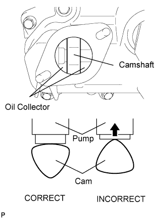

- HINT:
- When installing the fuel pump by following the procedure described above: By not using the crankshaft pointed side to push up the pump activation surface, it is easier to install the fuel pump and No. 2 fuel pipe later.
Pour 30 cc of engine oil through the cylinder head cover's fuel pump attachment hole into the cylinder head oil collector.
Apply a coat of engine oil to the pump activation cam and pump lifter part.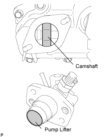
Install a new fuel pump insulator to the cylinder head cover. Then pass the 2 stud bolts through the holes of the fuel pump and set them on the insulator.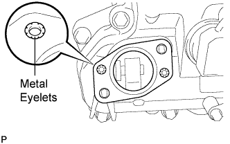
- NOTICE:
- Install the insulator so that the open sides of the metal eyelets are facing outward, as shown in the illustration.
Temporarily install the No.2 fuel pipe sub-assembly to the fuel pump assembly.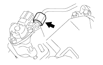
- NOTICE:
- Be careful not to damage the sealing surface of the fuel pipe when temporarily installing the fuel pipe.
Install the 2 nuts and tighten them in several passes.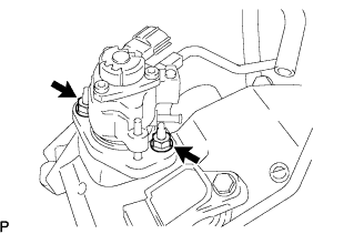
- Torque:
- 25 N*m{ 255 kgf*cm , 18 ft.*lbf }
Connect the fuel hose.
| 2. CONNECT NO. 2 FUEL PIPE |
Install the No. 2 fuel pipe to the delivery pipe with the 2 bolts.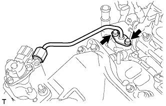
- Torque:
- 10 N*m{ 102 kgf*cm , 7 ft.*lbf }
Using a 19 mm union nut wrench, connect the fuel pipe.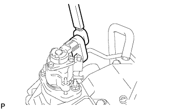
- Torque:
- 30 N*m{ 306 kgf*cm , 22 ft.*lbf }
- HINT:
- The torque shown above should be used for tightening without using union nut wrench. When the union nut wrench is used for tightening, the torque should be calculated based on the length of the union nut wrench (Click here).
Connect the connector to the fuel pump.
| 3. INSTALL NO. 1 FUEL PIPE |
Install the fuel pipe with the 2 bolts.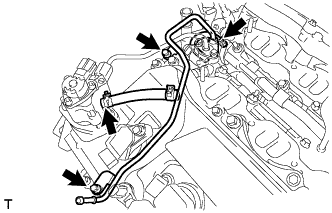
- Torque:
- 10 N*m{ 102 kgf*cm , 7 ft.*lbf }
Connect the 2 fuel hoses.
| 4. INSTALL FUEL PRESSURE PULSATION DAMPER |
Using SST, install a new gasket and the fuel pulsation damper to the fuel pump.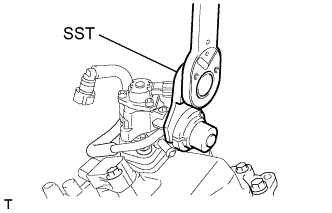
- Torque:
- 40 N*m{ 408 kgf*cm , 28 ft.*lbf }
- HINT:
- The torque shown above should be used for tightening without using SST. When the SST is used for tightening, the torque should be calculated based on the length of the SST (Click here).
| 5. CONNECT WATER HOSE JOINT |
Connect the water hose joint with the bolt.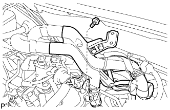
- Torque:
- 10 N*m{ 102 kgf*cm , 7 ft.*lbf }
| 6. INSTALL INTAKE MANIFOLD |
Install a new gasket and the intake manifold with the 4 bolts and 4 nuts.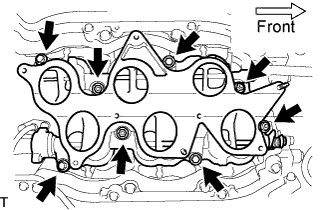
- Torque:
- 21 N*m{ 214 kgf*cm , 15 ft.*lbf }
Connect the SCV position sensor connector.
Connect the DC motor connector for the SCV.
| 7. INSTALL INTAKE AIR SURGE TANK |
Install a new gasket to the intake air surge tank.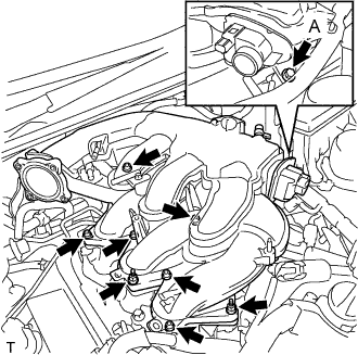
Using a 5 mm hexagon socket wrench, install the 6 bolts.
- Torque:
- Bolts except A:
- 18 N*m{ 184 kgf*cm , 13 ft.*lbf }
Install the bolt and 2 nuts to the intake air surge tank.
- Torque:
- Bolt A:
- 21 N*m{ 214 kgf*cm , 15 ft.*lbf }
- Nut:
- 16 N*m{ 163 kgf*cm , 12 ft.*lbf }
Install the surge tank stay to the intake air surge tank.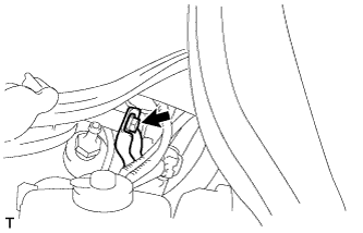
- Torque:
- 21 N*m{ 214 kgf*cm , 15 ft.*lbf }
Connect the water hose joint with the bolt.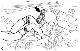
- Torque:
- 10 N*m{ 102 kgf*cm , 7 ft.*lbf }
Connect the ventilation hose to the intake air surge tank.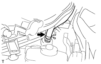
Connect the wire harness and hose to the intake air surge tank.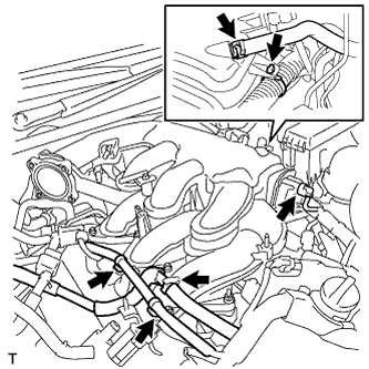
Connect the No. 1 vacuum switching valve assembly to the intake air surge tank.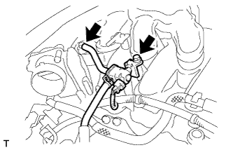
- Torque:
- 18 N*m{ 184 kgf*cm , 13 ft.*lbf }
Connect the vacuum hose to the intake air surge tank.
| 8. INSTALL THROTTLE WITH MOTOR BODY ASSEMBLY |
Check the throttle control motor operating sounds.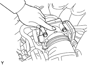
Turn the engine switch on (IG).
When pressing the accelerator pedal, check the operating sound of the running motor. Make sure that no friction noises emit from the motor.
If friction noise exists, replace the throttle body.
Check the throttle position sensor.
Connect the intelligent tester to the DLC3.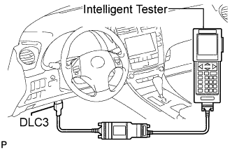
Turn the engine switch on (IG).
Turn the intelligent tester main switch ON.
Enter the following menus: DIAGNOSIS / ENHANCED OBD II / DATA LIST / THROTTLE POS AND THROTTLE POS #2.
Depress the accelerator pedal. When the throttle valve is fully opened, check that the value of the "Throttle Sensor Position" is within the specification.
- Standard throttle valve opening percentage:
- 60% or more
- NOTICE:
- When checking the standard throttle valve opening percentage, the shift lever should be in the N position.
| 9. INSTALL AIR CLEANER CAP WITH AIR CLEANER HOSE |
Install the air cleaner cap with air cleaner hose assembly with the 4 clamps and hose clamp.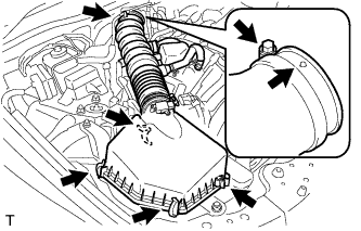
- HINT:
- Be sure to install the air cleaner assembly so that the screw part of the hose clamp is as shown in the illustration.
Install the VSV hose to the air cleaner hose.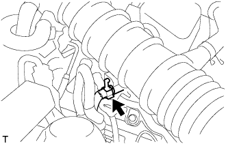
Connect the MAF meter connector and clamp to the air cleaner.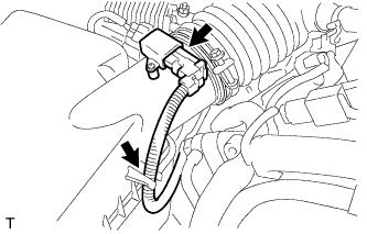
| 10. CONNECT NO. 2 VENTILATION HOSE |
Connect the ventilation hose to the cylinder head cover with the clamp.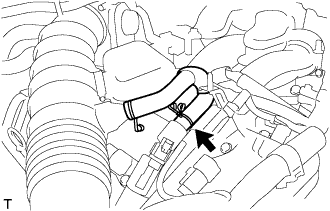
| 11. CONNECT CABLE TO NEGATIVE BATTERY TERMINAL |
- Torque:
- 5.4 N*m{ 55 kgf*cm , 48 in.*lbf }
| 12. ADD ENGINE COOLANT |
Tighten all the plugs and fill the radiator with TOYOTA Super Long Life Coolant (SLLC).
- Torque:
- 13 N*m{ 130 kgf*cm , 9 ft.*lbf } for cylinder block drain cock plug
Add engine coolant.
- Specified capacity:
- 9.1 liters (9.6 US qts, 8.0 lmp. qts)
- HINT:
- TOYOTA vehicles are filled with TOYOTA SLLC at the factory. In order to avoid damage to the engine cooling system and other technical problems, only use TOYOTA SLLC or similar high quality ethylene glycol based non-silicate, non-amine, non-nitrite, non-borate coolant with long-life hybrid organic acid technology (coolant with long-life hybrid organic acid technology consists of a combination of low phosphates and organic acids).
- TOYOTA vehicles are filled with TOYOTA SLLC at the factory. In order to avoid damage to the engine cooling system and other technical problems, only use TOYOTA SLLC or similar high quality ethylene glycol based non-silicate, non-amine, non-nitrite, non-borate coolant with long-life hybrid organic acid technology (coolant with long-life hybrid organic acid technology consists of a combination of low phosphates and organic acids).
- Contact your TOYOTA dealer for further details.
- Contact your TOYOTA dealer for further details.
Slowly pour coolant into the radiator reservoir until it reaches the FULL line.
Press the inlet and outlet radiator hoses several times by hand, and then check the level of the coolant.
If the coolant level is low, add coolant.
Install the radiator cap and reservoir cap.
Bleed air from the cooling system.
- NOTICE:
- Before starting the engine to warm up the engine, turn the A/C switch OFF.
Warm up the engine until the thermostat opens. While the thermostat is open, circulate the coolant for several minutes.
- HINT:
- The thermostat open timing can be confirmed by pressing the inlet radiator hose by hand, and checking when the engine coolant starts to flow inside the hose.
- NOTICE:
- When pressing the radiator hoses:
- Wear protective gloves.
- Wear protective gloves.
- Be careful as the radiator hoses are hot.
- Be careful as the radiator hoses are hot.
- Keep your hands away from the radiator fans.
- Keep your hands away from the radiator fans.
Maintain the engine speed at 2,000 to 2,500 rpm.
Press the inlet and outlet radiator hoses several times by hand to bleed air.
- NOTICE:
- When pressing the radiator hoses:
- Wear protective gloves.
- Wear protective gloves.
- Be careful as the radiator hoses are hot.
- Be careful as the radiator hoses are hot.
- Keep your hands away from the radiator fans.
- Keep your hands away from the radiator fans.
Stop the engine, and wait until the engine coolant cools down to ambient temperature.
- NOTICE:
- Do not remove the radiator cap while the engine and radiator are still hot. Pressurized, hot engine coolant and steam may be released and cause serious burns.
Check the coolant level in the radiator reservoir.
If the coolant level is low, add SLLC to the radiator reservoir FULL line.
| 13. CHECK FOR ENGINE COOLANT LEAKAGE |
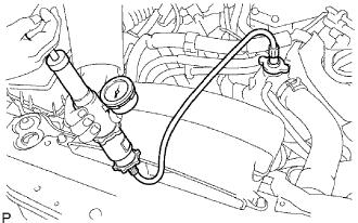 |
- NOTICE:
- Before performing each inspection, turn the A/C switch OFF.
- CAUTION:
- Do not remove the radiator cap while the engine and radiator are still hot. Pressurized, hot engine coolant and steam may be released and cause serious burns.
Fill the radiator with coolant and attach a radiator cap tester.
Warm up the engine.
Using a radiator cap tester, increase the pressure inside the radiator to 118 kPa (1.2 kgf*cm2, 17 psi), and check that the pressure does not drop.
If the pressure drops, check the hoses, radiator and water pump for leaks. If no external leaks are found, check the heater core, cylinder block and cylinder head.
| 14. CHECK FOR FUEL LEAKAGE |
Connect the intelligent tester to the DLC3.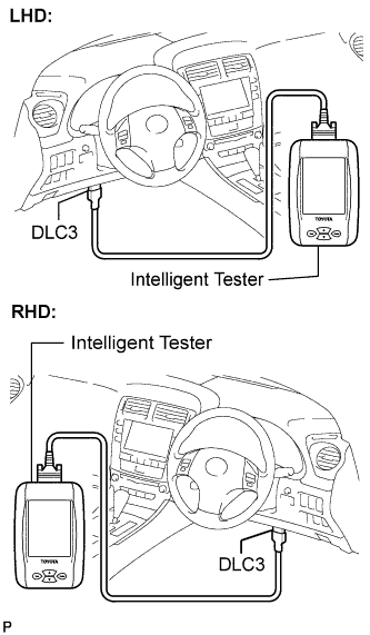
Turn the engine switch on (IG).
- NOTICE:
- Do not start the engine.
Push the intelligent tester main switch ON.
Select the following menus: Powertrain / Engine / Active Test / Control the Fuel Pump /Speed.
Check the fuel pump operation.
Check for pressure in the fuel inlet tube from the fuel line. Check that sound of fuel flowing in the fuel tank can be heard.
If no sound can be heard, check the integration relay, fuel pump, ECM and wiring connector.
Check for fuel leaks.
Check that there are no fuel leaks anywhere on the system after performing maintenance.
If there is a fuel leak, repair or replace parts as necessary.
| 15. CHECK FOR ENGINE OIL LEAKS |
| 16. INSTALL COWL TOP VENTILATOR LOUVER SUB-ASSEMBLY |
Engage the 11 claws.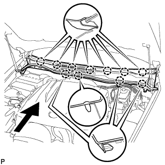
Install the cowl top ventilator louver sub-assembly with the 2 clips.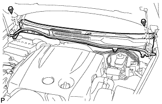
| 17. INSTALL FRONT WIPER ARM AND BLADE ASSEMBLY LH |
Operate the wiper, and stop the windshield wiper motor at the automatic stop position.
Clean the wiper arm serrations.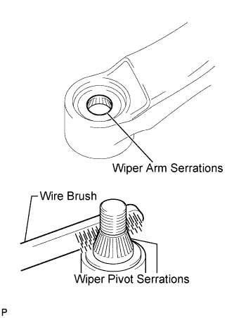
Clean the wiper pivot serrations with a wire brush (when reinstalling).
Install the front wiper arm and blade assembly LH with the nut at the position as shown in the illustration.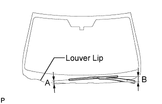
- Torque:
- 22 N*m{ 224 kgf*cm , 16 ft.*lbf }
- HINT:
- Hold the arm hinge by hand to fasten the nut.
Area
Measurement
A
15 to 30 mm (0.59 to 1.18 in.)
B
Approx. 40 mm (1.57 in.)
| 18. INSTALL FRONT WIPER ARM AND BLADE ASSEMBLY RH |
Operate the wiper, and stop the windshield wiper motor at the automatic stop position.
Clean the wiper arm serrations.
Clean the wiper pivot serrations with a wire brush (when reinstalling).
Install the front wiper arm and blade assembly RH with the nut at the position as shown in the illustration.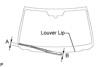
- Torque:
- 22 N*m{ 224 kgf*cm , 16 ft.*lbf }
- HINT:
- Hold the arm hinge by hand to fasten the nut.
Area
Measurement
A
18.5 to 33.5 mm (0.73 to 1.32 in.)
B
Approx. 20 mm (0.79 in.)
Operate the front wipers while spraying washer fluid on the windshield glass. Make sure that the front wipers function properly and there is no interference with the vehicle body.
| 19. INSTALL FRONT WIPER ARM HEAD CAP |
Install the front wiper arm head cap.
- HINT:
- Use the same procedures for the RH side and the LH side.
| 20. INSTALL ROOF DRIP SIDE FINISH MOULDING LH |
| 21. INSTALL ROOF DRIP SIDE FINISH MOULDING RH |
| 22. INSTALL FRONT UPPER FENDER PROTECTOR LH |
Engage the claw and the 3 clips, then install the front upper fender protector LH.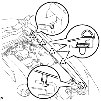
Engage the clip on the rubber portion of the cowl top ventilator louver sub-assembly to the front fender protector upper LH.
| 23. INSTALL FRONT UPPER FENDER PROTECTOR RH |
- HINT:
- Installation procedure of the RH side is the same as that of the LH side.
| 24. INSTALL V-BANK COVER SUB-ASSEMBLY |
Engage the 2 clips on the front of the cover, and then engage the clip on the rear to install the V-bank cover.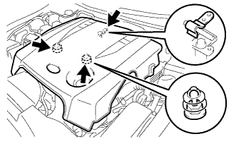
- NOTICE:
- Be sure to engage the clips securely.
- Do not apply excessive force or do not hit the cover to engage the clips. This may cause the cover to break.
- Be sure to engage the clips securely.
| 25. INSTALL ENGINE ROOM SIDE COVER LH |
Install the side cover with the 5 clips.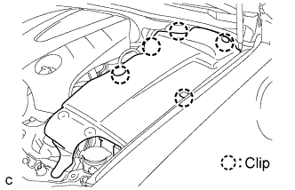
| 26. INSTALL ENGINE ROOM SIDE COVER RH |
Install the side cover with the 2 clips.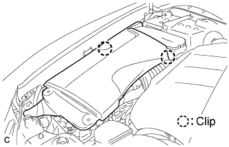
| 27. INSTALL COOL AIR INTAKE DUCT SEAL |
Install the intake duct seal with the 11 clips.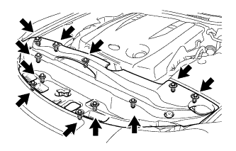
| 28. CHECK FUNCTION OF THROTTLE WITH MOTOR BODY ASSEMBLY |
Check the throttle control motor operating sounds.
Turn the engine switch on (IG).
When pressing the accelerator pedal, check the operating sound of the running motor. Make sure that no friction noises emit from the motor.
If friction noise exists, replace the throttle body.
Check the throttle position sensor.
Connect the intelligent tester to the DLC3.
Turn the engine switch on (IG).
Turn the intelligent tester main switch ON.
Enter the following menus: DIAGNOSIS / ENHANCED OBD II / DATA LIST / THROTTLE POS AND THROTTLE POS #2.
Depress the accelerator pedal. When the throttle valve is fully opened, check that the value of the "Throttle Sensor Position" is within the specification.
- Standard throttle valve opening percentage:
- 60% or more
- NOTICE:
- When checking the standard throttle valve opening percentage, the shift lever should be in the N position.
| 29. PERFORM INITIALIZATION |
Perform initialization (Click here).
- HINT:
- Certain systems need to be initialized after reconnecting the cable to the negative (-) battery terminal.