REASSEMBLY
Removal / installation
| 1. INSTALL GENERATOR DRIVE END FRAME BEARING |

Using SST and a press, press in a new generator drive end frame bearing.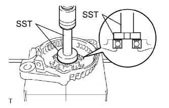

- SST
- 09950-60010
(09951-00470)
09950-70010 (09951-07100)
Fit the tabs on the retainer plate into the cutouts on the drive end frame to install the retainer plate.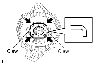
Install the 4 screws.
- Torque:
- 2.3 N*m{ 23 kgf*cm , 20 in.*lbf }
| 2. INSTALL GENERATOR ROTOR ASSEMBLY |
Place the drive end frame on the clutch pulley.
Install the rotor assembly to the drive end frame.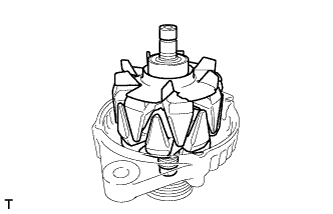
Place a new generator washer on the generator rotor.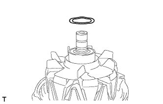
| 3. INSTALL GENERATOR COIL ASSEMBLY |
Using SST and a press, press in the generator coil assembly to the drive end frame.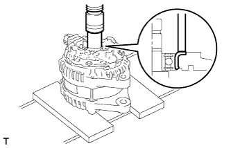
- SST
- 09612-70100
(09612-07240)
Install the generator coil assembly with the 4 bolts.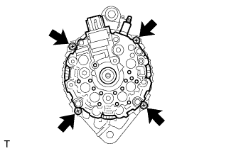
- Torque:
- 5.8 N*m{ 59 kgf*cm , 51 in.*lbf }
| 4. INSTALL GENERATOR BRUSH HOLDER ASSEMBLY |
While pushing the 2 brushes into the generator brush holder assembly, insert a φ1.0 mm (0.039 in.) pin into the brush holder hole.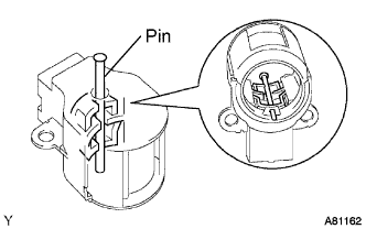
Install the generator brush holder assembly to the generator coil with the 2 screws.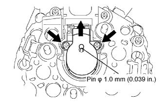
- Torque:
- 1.8 N*m{ 18 kgf*cm , 16 in.*lbf }
Pull out the pin from the generator brush holder.
| 5. INSTALL TERMINAL INSULATOR |
Install the terminal insulator to the generator coil.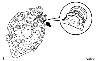
| 6. INSTALL GENERATOR REAR END COVER |
Install the generator rear end cover to the generator coil with the 3 nuts.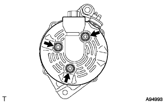
- Torque:
- 4.6 N*m{ 47 kgf*cm , 41 in.*lbf }
| 7. INSTALL CLUTCH PULLEY |
Temporarily install the clutch pulley onto the rotor shaft.
Set SST (A) and (B).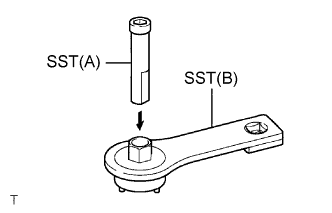
- SST
- 09820-63020
Clamp SST (A) in a vise.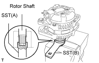
Place the rotor shaft end into SST (A).
Fit SST (B) to the clutch pulley.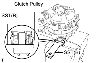
Tighten the pulley by turning SST (B) in the direction shown in the illustration.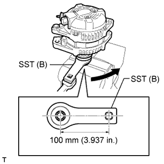
- Torque:
- 111 N*m{ 1,127 kgf*cm , 81 ft.*lbf }
- NOTICE:
- The torque shown above should be used for tightening without using SST. When the SST is used for tightening, the torque should be calculated based on the length of the SST (Click here).
Remove the generator assembly from the SST.
Check that the clutch pulley rotates smoothly.
Install the new clutch pulley cap to the clutch pulley.