P0717
Diagnostic trouble codes
DESCRIPTION
This sensor detects the rotation speed of the turbine which shows the input revolution of transmission. By comparing the input turbine speed signal (NT) with the counter gear speed sensor signal (SP2), the ECM detects the shift timing of the gears and appropriately controls the engine torque and hydraulic pressure according to various conditions. Thus, providing smooth gear shift.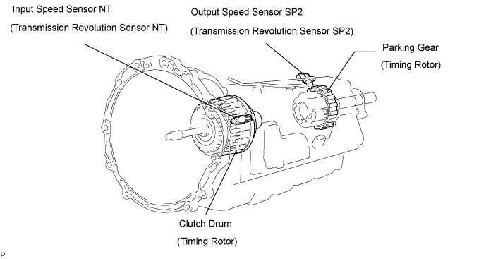

| DTC No. |
DTC Detection Condition |
Trouble Area |
| P0717 |
|
|
Check the waveform between the terminals NT+ and NT- of the ECM connector.
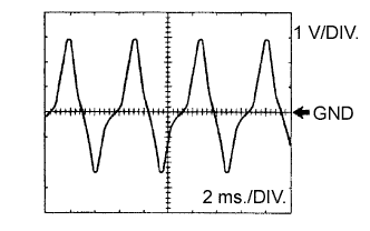
- Standard:
- Refer to the illustration.
| Terminal |
NT+ - NT- |
| Tool setting |
1 V/DIV, 2 ms./DIV. |
| Vehicle condition |
Engine idle speed (P or N position) |
MONITOR DESCRIPTION
This DTC indicates that pulse is not output from the speed sensor NT (Turbine (input) speed sensor ) or is output only little. The NT terminal of the ECM detects the revolving signal from speed sensor (NT) (input RPM). The ECM outputs a gearshift signal comparing the input speed sensor (NT) with the output speed sensor (SP2).While the vehicle is operating in the 4th, 5th or 6th gear position in the shift position of D, if the input shaft revolution is less than 300 rpm*1 although the output shaft revolution is 300 rpm or more*2, the ECM detects the trouble, illuminates the MIL and stores the DTC.
*1: Pulse is not output or is irregularly output.
*2: The vehicle speed is approx. 50 km/h (31 mph) or more.
WIRING DIAGRAM
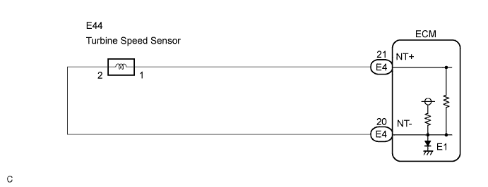
INSPECTION PROCEDURE
| DATA LIST |
- HINT:
- Using the intelligent tester Data List allows switch, sensor, actuator and other item values to be read without removing any parts. Reading the Data List early in troubleshooting is one way to shorten labor time.
- NOTICE:
- In the table below, the values listed under "Normal Condition" are reference values. Do not depend solely on these reference values when deciding whether a part is faulty or not.
Warm up the engine.
Turn the engine switch off.
Connect the intelligent tester to the DLC3.
Turn the engine switch on (IG) position.
Turn on the tester.
Select the item "Enter / Powertrain / ECT / Data List".
Follow the instructions on the tester and read the Data List.
Item
Measurement Item/
Range (display)
Normal Condition
SPD (NT)
Input Turbine Speed/
display: 50 r/min
- HINT:
- Lock-up ON (After warming up the engine);
Input Turbine speed (NT) equal to the engine speed.
- Lock-up OFF (Idling at N position);
Input Turbine speed (NT) nearly equal to the engine speed.
- Lock-up ON (After warming up the engine);
- HINT:
- SPD (NT) is always 0 while driving:
Open or short in the sensor or circuit.
- SPD (NT) is always more than 0 and less than 300 rpm while driving the vehicle at 50 km/h (31 mph) or more:
Sensor trouble, improper installation, or intermittent connection trouble of the circuit.
- SPD (NT) is always 0 while driving:
| 1. INSPECT SPEED SENSOR INSTALLATION |

Check the speed sensor (NT) installation.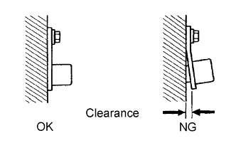
- OK:
- The installation bolt is tightened properly and there is no clearance between the sensor and transmission case.
|
|
||||

| OK | |
 |
| 2. INSPECT SPEED SENSOR (NT) |
Disconnect the speed sensor connector from the transmission.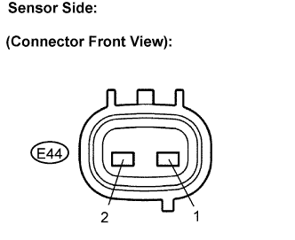
Measure the resistance according to the value(s) in the table below.
- Standard resistance:
Tester Connection
Specified Condition
20°C (68°F)
1 - 2
560 to 680 Ω
|
|
||||
| OK | |
|
| 3. CHECK HARNESS AND CONNECTOR (SPEED SENSOR - ECM) |
Connect the speed sensor connector.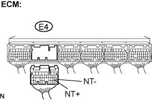
Disconnect the ECM connector.
Measure the resistance according to the value(s) in the table below.
- Standard resistance:
Tester Connection
Specified Condition
20°C (68°F)
E4-21 (NT+) - E4-20 (NT-)
560 to 680 Ω
Measure the resistance according to the value(s) in the table below.
- Standard resistance (Check for short):
Tester Connection
Specified Condition
E4-21 (NT+) - Body ground
10 kΩ or higher
E4-20 (NT-) - Body ground
↑
|
|
||||
| OK | ||
 |
||
| ||