DIAGNOSIS SYSTEM
Troubleshooting
| DESCRIPTION |
The network gateway ECU controls the functions of the multiplex communication system on the vehicle. Data of the multiplex communication system and the Diagnostic Trouble Codes (DTC) can be read through the Data Link Connector 3 (DLC3) of the vehicle.
| CHECK DLC3 |
The vehicle's ECM uses the ISO 15765-4 for communication protocol. The terminal arrangement of the DLC3 complies with ISO 15031-03 and matches the ISO 15765-4 format.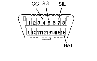

Symbols (Terminal No.)
Terminal Description
Condition
Specified Condition
SIL (7) - SG (5)
Bus "+" line
During transmission
Pulse generation
CG (4) - Body ground
Chassis ground
Always
Below 1 Ω
SG (5) - Body ground
Signal ground
Always
Below 1 Ω
BAT (16) - Body ground
Battery positive
Always
11 to 14 V
- If the result is not as specified, the DLC3 may have a malfunction. Repair or replace the harness and connector.
- If the result is not as specified, the DLC3 may have a malfunction. Repair or replace the harness and connector.
Intelligent tester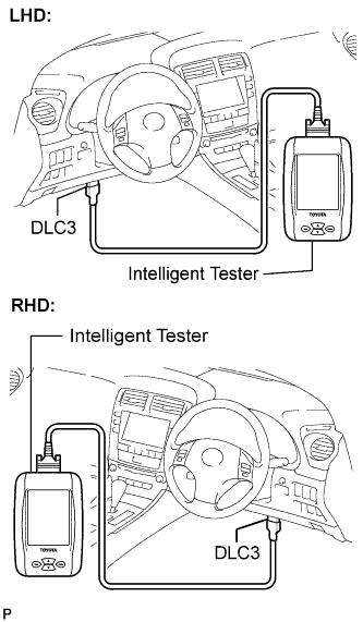
- HINT:
- Connect the cable of the intelligent tester to the DLC3, turn the engine switch on (IG) and attempt to use the tester. If the display indicates that a communication error has occurred, there is a problem either with the vehicle or with the tester.
- If communication is normal when the tester is connected to another vehicle, inspect the DLC3 of the original vehicle.
- If communication is still not possible when the tester is connected to another vehicle, the problem may be in the tester itself. Consult the Service Department listed in the tester's instruction manual.
- If communication is normal when the tester is connected to another vehicle, inspect the DLC3 of the original vehicle.
| INSPECT BATTERY VOLTAGE |
- Standard voltage:
- 11 to 14 V