Open in CAN Main Bus Line
Circuit diagnosis
DESCRIPTION
There may be an open circuit in the CAN main bus line and/or the DLC3 branch line when the resistance between terminals 6 (CANH) and 14 (CANL) of the DLC3 is 69 Ω or more.| Symptom |
Trouble Area |
| The resistance between terminals 6 (CANH) and 14 (CANL) of the DLC3 is 69 Ω or more. |
|
WIRING DIAGRAM
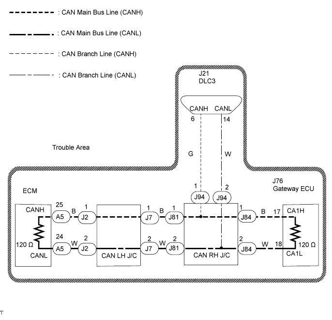

INSPECTION PROCEDURE
| 1. CHECK DLC3 |

Turn the engine switch off.
Measure the resistance according to the value(s) in the table below.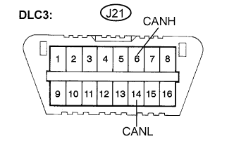
- Standard resistance:
Tester Connection
Condition
Specified Value
Result
J21-6 (CANH) -J21-14 (CANL)
Engine switch off
108 to 132 Ω
A
J21-6 (CANH) - J21-14 (CANL)
Engine switch off
132 Ω or higher
B
- NOTICE:
- When the measured value is 132 Ω or more and a CAN communication system diagnostic trouble code is output, there may be a fault besides disconnection of the DLC3 branch line. For that reason, troubleshooting should be performed again from "HOW TO PROCEED WITH TROUBLESHOOTING" (Click here ) after repairing the trouble area.
|
|
||||

| A | |
 |
| 2. CHECK FOR OPEN IN CAN MAIN BUS LINE (BUS CHECK) |
Perform "Communication Bus Check" using the intelligent tester (Click here).
- Result:
Specified Condition
Proceed to
"BODY/GATEWAY" only is not displayed
A
"ENGINE and ECT" only are not displayed
B
Others
C
|
|
||||
|
|
||||

| A | |
|
| 3. CHECK FOR OPEN IN CAN MAIN BUS LINE (GATEWAY ECU - CAN RH J/C) |
Turn the engine switch off.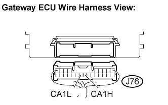
Disconnect the gateway ECU connector (J76).
Measure the resistance according to the value(s) in the table below.
- Standard resistance:
Tester Connection
Condition
Specified Value
J76-17 (CA1H) - J76-18 (CA1L)
Engine switch off
108 to 132 Ω
|
|
||||
| OK | ||
 |
||
| ||
| 4. CHECK FOR OPEN IN CAN MAIN BUS LINE (ECM - CAN RH J/C) |
Turn the engine switch off.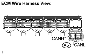
Disconnect the ECM connector (A5).
Measure the resistance according to the value(s) in the table below.
- Standard resistance:
Tester Connection
Condition
Specified Value
A5-25 (CANH) - A5-24 (CANL)
Engine switch off
108 to 132 Ω
|
|
||||
| NG | |
|
| 5. RECONNECT CONNECTOR |
Reconnect the ECM connector (A5).
| NEXT | |
|
| 6. CHECK FOR OPEN IN CAN MAIN BUS LINE (CAN LH J/C - ECM) |
Disconnect the CAN main bus line connector (J2) from the CAN LH J/C B side (with earth terminal).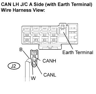
Measure the resistance according to the value(s) in the table below.
- Standard resistance:
Tester Connection
Condition
Specified Value
J2-1 (CANH) - J2-2 (CANL)
Engine switch off
108 to 132 Ω
|
|
||||
| OK | ||
|
||
| ||
| 7. CHECK FOR OPEN IN CAN MAIN BUS LINE (ECM - CAN LH J/C) |
Turn the engine switch off.
Disconnect the ECM connector (A5).
Measure the resistance according to the value(s) in the table below.
- Standard resistance:
Tester Connection
Condition
Specified Value
A5-25 (CANH) - A5-24 (CANL)
Engine switch off
108 to 132 Ω
|
|
||||
| NG | |
|
| 8. RECONNECT CONNECTOR |
Reconnect the ECM connector (A5).
| NEXT | |
|
| 9. CHECK FOR OPEN IN CAN MAIN BUS LINE (GATEWAY ECU - CAN LH J/C) |
Disconnect the gateway ECU connector (J76).
Measure the resistance according to the value(s) in the table below.
- Standard resistance:
Tester Connection
Condition
Specified Value
J76-17 (CA1H) - J76-18 (CA1L)
Engine switch off
108 to 132 Ω
|
|
||||
| NG | |
|
| 10. RECONNECT CONNECTOR |
Reconnect the gateway ECU connector (J76).
| NEXT | |
|
| 11. CHECK FOR OPEN IN CAN MAIN BUS LINE (CAN RH J/C - GATEWAY ECU) |
Disconnect the CAN main bus line connector (J84) from the CAN RH J/C B side (without earth terminal).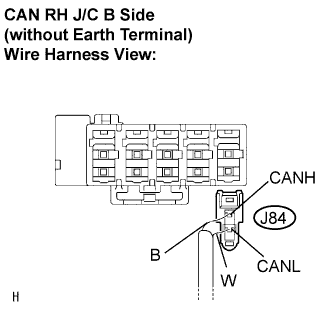
- NOTICE:
- Before disconnecting the connector, make a note of where it is connected.
- Reconnect the connector to its original position.
- Before disconnecting the connector, make a note of where it is connected.
Measure the resistance according to the value(s) in the table below.
- Standard resistance:
Tester Connection
Condition
Specified Value
J84-1 (CANH) - J84-2 (CANL)
Engine switch off
108 to 132 Ω
|
|
||||
| OK | |
|
| 12. RECONNECT CONNECTOR |
Reconnect the CAN main bus line connector (J84) to the CAN RH J/C B side (without earth terminal).
| NEXT | |
|
| 13. CHECK FOR OPEN IN CAN MAIN BUS LINE (ECM - CAN LH J/C) |
Disconnect the CAN main bus line connector (J2) from the CAN LH J/C A side (with earth terminal).
Measure the resistance according to the value(s) in the table below.
- Standard resistance:
Tester Connection
Condition
Specified Value
J2-1 (CANH) - J2-2 (CANL)
Engine switch off
108 to 132 Ω
|
|
||||
| OK | ||
|
||
| ||