CAN Bus Line
Circuit diagnosis
DESCRIPTION
When any DTC for the CAN communication system is output, first measure the resistance between the terminals of the DLC3 to specify the trouble area. Then check that there is no short in the CAN main bus line, between the CAN bus lines, to B+, or to GND.WIRING DIAGRAM
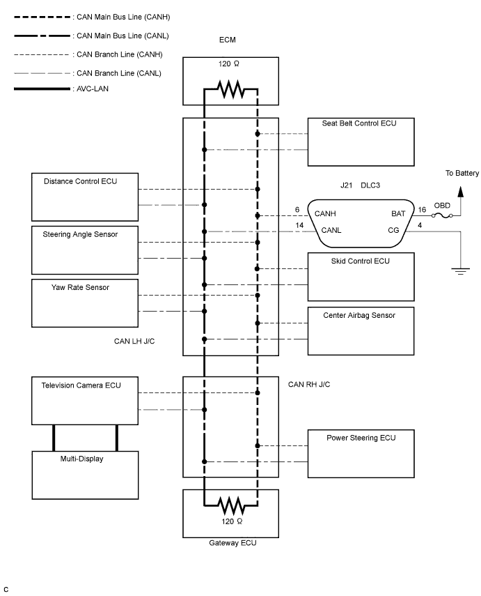

INSPECTION PROCEDURE
| 1. CHECK CAN BUS LINE (MAIN BUS LINE FOR OPEN, BUS LINES FOR SHORT CIRCUIT) |

Turn the engine switch off.
Measure the resistance according to the value(s) in the table below.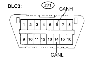
- Standard resistance:
Tester Connection
Condition
Specified Value
J21-6 (CANH) - J21-14 (CANL)
Engine switch off
54 to 69 Ω
- Result:
Result
Proceed to
See Procedure
OK
A
-
69 Ω or higher
B
Click here
Below 54 Ω
C
Click here
|
|
||||
|
|
||||

| A | |
 |
| 2. CHECK CAN BUS LINE (SHORT TO B+ IN CAN BUS LINE) |
Measure the resistance according to the value(s) in the table below.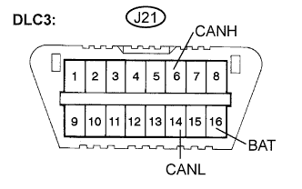
- Standard resistance:
Tester Connection
Condition
Specified Value
J21-6 (CANH) - J21-16 (BAT)
Engine switch off
1 MΩ or higher
J21-14 (CANL) - J21-16 (BAT)
Engine switch off
1 MΩ or higher
- See page:
Result
See Procedure
OK
Go to step 3
NG
Click here
|
|
||||
| OK | |
|
| 3. CHECK CAN BUS LINE (SHORT TO GND IN CAN BUS LINE) |
Measure the resistance according to the value(s) in the table below.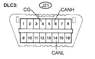
- Standard resistance:
Tester Connection
Condition
Specified Value
J21-4 (CG) - J21-6 (CANH)
Engine switch off
1 MΩ or higher
J21-4 (CG) - J21-14 (CANL)
Engine switch off
1 MΩ or higher
- See page:
Result
See Procedure
OK
Click here
NG
Click here
|
|
||||
| OK | ||
 |
||
| ||