Short to GND in CAN Bus Line
Circuit diagnosis
DESCRIPTION
A short to GND is suspected the CAN bus line when the resistance between terminals 4 (CG) and 6 (CANH), or terminals 4 (CG) and 14 (CANL) of the DLC3 is below 1 kΩ.| Symptoms |
Trouble Area |
| The resistance between terminals 6 (CANH) and 4 (CG), or terminals 14 (CANL) and 4 (CG) of the DLC3 is below 1 kΩ. |
|
WIRING DIAGRAM
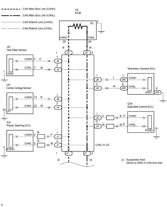

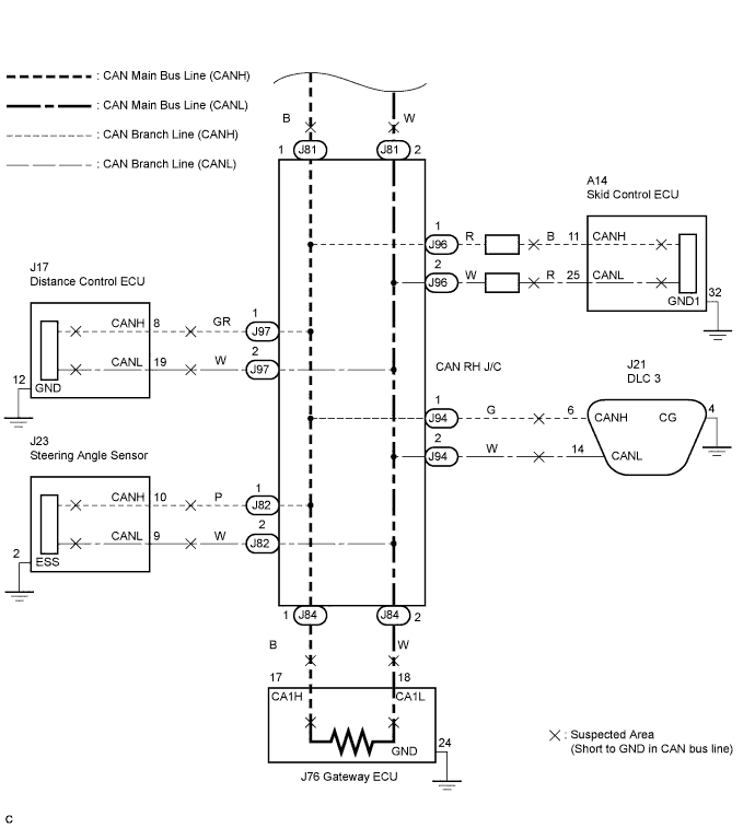
INSPECTION PROCEDURE
| 1. CHECK FOR SHORT TO GND IN CAN BUS LINE |

Turn the engine switch off.
Disconnect the DLC3 branch line connector (J94) from the CAN RH J/C A side (with earth terminal).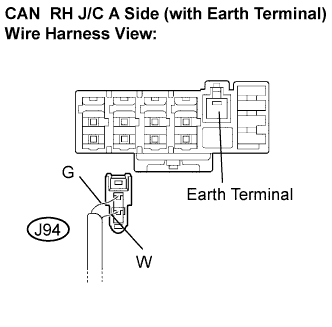
- NOTICE:
- Before disconnecting the connector, make a note of where it is connected.
- Reconnect the connector to its original position.
- Before disconnecting the connector, make a note of where it is connected.
Measure the resistance according to the value(s) in the table below.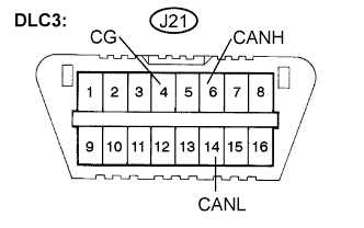
- Standard resistance:
Tester Connection
Condition
Specified Value
J21-6 (CANH) - J21-4 (CG)
Engine switch off
1 MΩ or higher
J21-14 (CANL) - J21-4 (CG)
Engine switch off
1 MΩ or higher
|
|
||||

| OK | |
 |
| 2. RECONNECT CONNECTOR |
Reconnect the DLC3 branch line connector (J94) to the CAN RH J/C A side (with earth terminal).
| NEXT | |
|
| 3. CHECK FOR SHORT TO GND IN CAN BUS LINE |
Disconnect connectors from the CAN LH J/C or CAN RH J/C one at a time.
- HINT:
- Disconnect the ECU and sensor connectors other than the DLC3 branch lines and CAN main bus lines between the CAN LH J/C and CAN RH J/C.
Using an ohmmeter, measure the resistance between terminals 6 (CANH) and 4 (CG), and between terminals 14 (CANL) and 4 (CG) of the DLC3 each time a connector is disconnected.
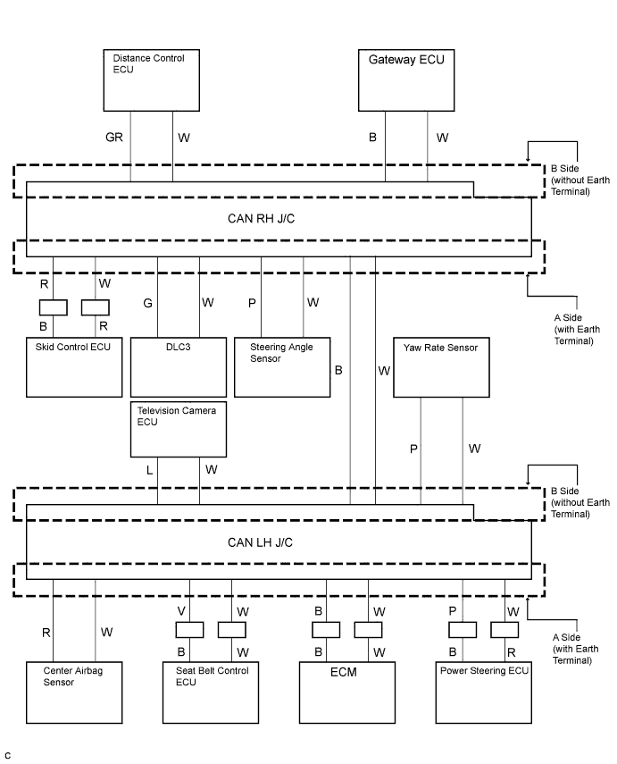
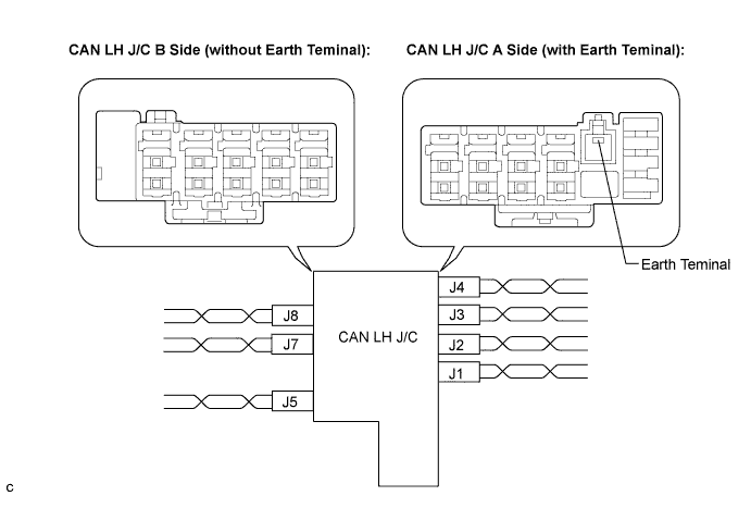
Wiring color: CAN LH J/C A Side (with Earth Terminal)
Code
Color (CANH Side)
Color (CANL Side)
Power steering ECU
J1
P
W
ECM
J2
B
W
Seat belt control ECU
J3
V
W
Center airbag sensor
J4
R
W
Wiring color: CAN LH J/C B Side (without Earth Terminal)
Code
Color (CANH Side)
Color (CANL Side)
Yaw rate sensor
J5
P
W
CAN main bus line (bus line connecting CAN LH J/C and CAN RH J/C)
J7
B
W
Television camera ECU
J8
L
W
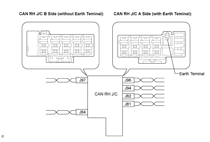
Wiring color: CAN RH J/C A Side (with Earth Terminal)
Code
Color (CANH Side)
Color (CANL Side)
CAN main bus line (bus line connecting CAN RH J/C and CAN LH J/C)
J81
B
W
Steering angle sensor
J82
P
W
DLC3
J94
G
W
Skid control ECU
J96
R
W
Wiring color: CAN RH J/C B Side (without Earth Terminal)
Code
Color (CANH Side)
Color (CANL Side)
Gateway ECU
J84
B
W
Distance control ECU
J97
GR
W
- NOTICE:
- Do not reconnect the disconnected connectors until this inspection is complete because there may be a short to GND in 2 or more CAN bus lines.
- Result:
Symptom
Proceed to
The resistance between terminals 6 (CANH) and 4 (CG), or the resistance between 14 (CANL) and 4 (CG) is still below 1 kΩ when all the specified connectors are disconnected from the CAN J/C. (There is a short to GND in the CAN main bus lines between the CAN LH J/C and CAN RH J/C.)
A
The resistance between terminals 6 (CANH) and 4 (CG), or the resistance between 14 (CANL) and 4 (CG) becomes normal (1 kΩ or more) when a connector is disconnected from the CAN J/C. (There is a short to GND in one of the areas that relate to the disconnected bus lines.)
B
When there is a short to GND in one or more of the bus lines that connect to an ECU (or sensor):
Reconnect all of the connectors to the CAN J/C, except for the one that was disconnected last (the bus line that is shorted to GND). Check that the resistance shown on the tester is normal (1 kΩ or more) to confirm that there is a short to GND in the one branch line only.
- HINT:
- The connectors connected to the CAN J/C can be distinguished according to the color of the communication bus lines and the shape of the connectors.
- Reconnecting the connectors to non-specified positions on the CAN J/C does not affect system operation. However, it is preferred to reconnect the connectors to their specified positions to avoid negative effects on the wiring such as tension on the wiring harnesses, and to make future maintenance easier.
- The connectors connected to the CAN J/C can be distinguished according to the color of the communication bus lines and the shape of the connectors.
|
|
||||
| B | |
|
| 4. RECONNECT CONNECTOR |
Reconnect the connector of the bus line that is shorted to GND to the CAN J/C (the connector that caused the bus line resistance to change to 1 kΩ or more when it was disconnected).
| NEXT | |
|
| 5. CHECK FOR SHORT TO GND IN CAN BUS LINE |
Disconnect the connector that includes terminals CANH and CANL from the ECU (or sensor) to which the bus line shorted to GND is connected. (Click here)
Measure the resistance according to the value(s) in the table below.
- Standard resistance:
Tester Connection
Condition
Specified Value
J21-6 (CANH) - J21-4 (CG)
Engine switch off
1 kΩ or higher
J21-14 (CANL) - J21-4 (CG)
Engine switch off
1 kΩ or higher
- HINT:
- If the resistance changes to 1 kΩ or higher when the connector is disconnected from the ECU (or sensor), there may be a short in the ECU (or sensor).
|
|
||||
| OK | ||
 |
||
| ||