ECM Power Source Circuit
Circuit diagnosis
DESCRIPTION
When the engine switch is turned to on, the battery voltage is applied to terminal IGSW of the ECM. The ECM MREL output signal causes a current to flow to the coil, closing the contacts of the EFI MAIN relay and supplying power to terminal +B of the ECM.If the engine switch is turned to off, the ECM holds the EFI MAIN relay ON for a maximum of 2 seconds to allow for the initial setting of the throttle valve.
When the engine switch is turned on (IG), voltage from the ECM's MREL terminal flows to the integration relay (EFI MAIN relay). This causes the contacts of the integration relay (EFI MAIN relay) to close, which supplies power to terminal +B or +B1 of the ECM.
WIRING DIAGRAM
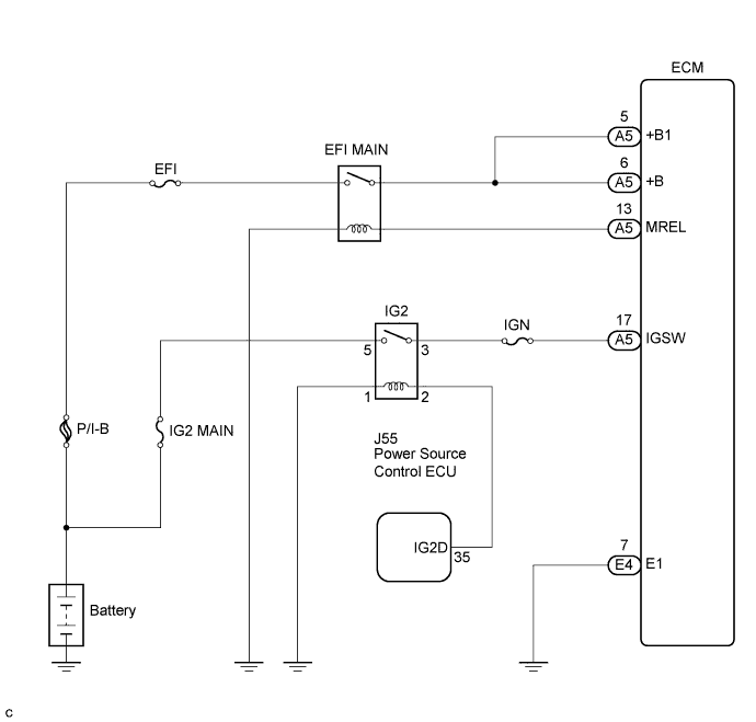

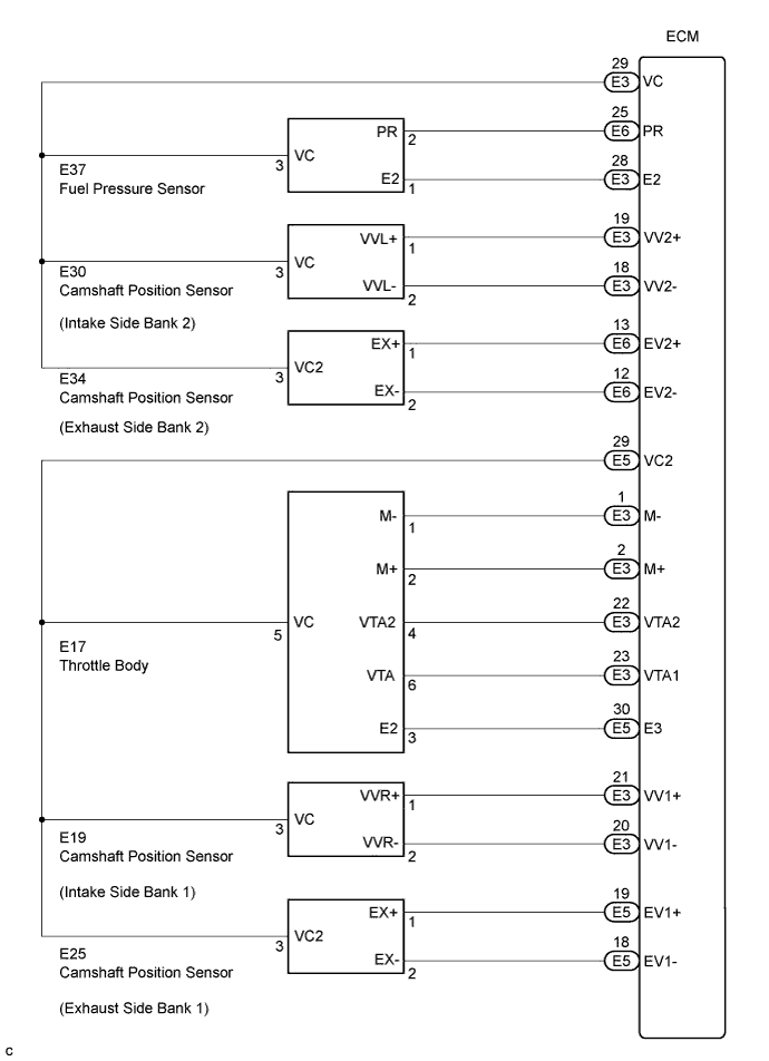
INSPECTION PROCEDURE
| 1. INSPECT ECM (+B, +B1 VOLTAGE) |

Turn the engine switch on (IG).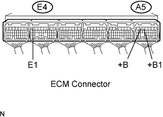
Measure the voltage of the A5 and E4 ECM connectors.
- Standard voltage:
Tester Connection
Specified Condition
+B (A5-6) - E1 (E4-7)
9 to 14 V
+B1 (A5-5) - E1 (E4-7)
9 to 14 V
|
|
||||

| NG | |
 |
| 2. CHECK HARNESS AND CONNECTOR (ECM - BODY GROUND) |
Disconnect the E4 ECM connector.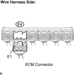
Measure the resistance of the wire harness side connector.
- Standard resistance (Check for open):
Tester Connection
Specified Condition
E1 (E4-7) - Body ground
Below 1 Ω
Reconnect the ECM connector.
|
|
||||
| OK | |
|
| 3. INSPECT ECM (IGSW VOLTAGE) |
Turn the engine switch on (IG).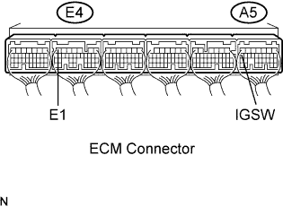
Measure the voltage of the A5 and E4 ECM connectors.
- Standard voltage:
Tester Connection
Specified Condition
IGSW (A5-17) - E1 (E4-7)
9 to 14 V
|
|
||||

| NG | |
|
| 4. CHECK FUSE (IGN FUSE) |
Remove the IGN fuse from the cowl side junction block RH.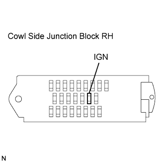
Measure the resistance of the IGN fuse .
- Standard resistance:
- Below 1 Ω
Reinstall the IGN fuse.
|
|
||||
| OK | |
|
| 5. INSPECT IG2 RELAY |
Remove the IG2 relay from the engine room J/B and R/B No. 2.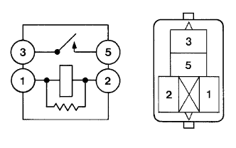
Measure the resistance of the IG2 relay.
- Standard resistance:
Tester Connection
Specified Condition
3 - 5
10 kΩ or higher
3 - 5
Below 1 Ω
(when battery voltage applied to terminals 1 and 2)
|
|
||||
| OK | ||
 |
||
| ||
| 6. INSPECT ECM (MREL VOLTAGE) |
Turn the engine switch on (IG).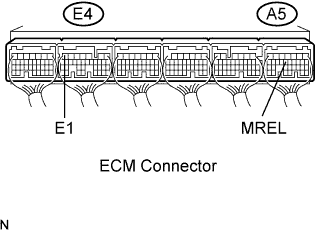
Measure the voltage of the A5 and E4 ECM connectors.
- Standard voltage:
Tester Connection
Specified Condition
MREL (A5-13) - E1 (E4-7)
9 to 14 V
|
|
||||
| OK | |
|
| 7. CHECK FUSE (EFI FUSE) |
Remove the EFI fuse from the engine room J/B and R/B No. 2.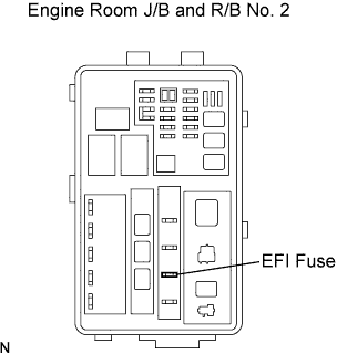
Measure the resistance of the EFI fuse.
- Standard resistance:
- Below 1 Ω
Reinstall the EFI fuse.
|
|
||||
| OK | |
|
| 8. INSPECT INTEGRATION RELAY (EFI MAIN RELAY) |
Remove the integration relay from the engine room J/B and R/B No. 2.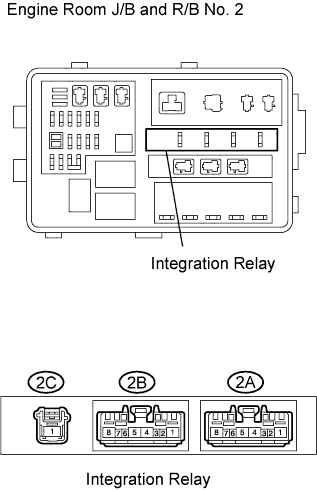
Measure the resistance of the EFI MAIN relay.
- Standard resistance:
Tester Connection
Specified Condition
2C-1 - 2A-8
10 kΩ or higher
Below 1 Ω
(when battery voltage applied to terminals 2A-6 and 2A-7)
|
|
||||
| OK | |
|
| 9. CHECK HARNESS AND CONNECTOR (INTEGRATION RELAY- ECM, INTEGRATION RELAY - BODY GROUND) |
Check the harness and the connectors between the integration relay and the ECM.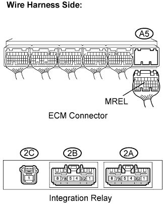
Remove the integration relay from the engine room J/B and R/B No. 2.
Disconnect the A5 ECM connector.
Measure the resistance of the wire harness side connectors.
- Standard resistance (Check for open):
Tester Connection
Specified Condition
2A-6 - MREL (A5-13)
Below 1 Ω
- Standard resistance (Check for short):
Tester Connection
Specified Condition
2A-6 or MREL (A5-13) - Body ground
10 kΩ or higher
Check the harness and the connectors between the integration relay and body ground.
Remove the integration relay from the engine room J/B and R/B No. 2.
Measure the resistance of the wire harness side connector and body ground.
- Standard resistance (Check for open):
Tester Connection
Specified condition
2A-7 - Body ground
Below 1 Ω
|
|
||||
| OK | ||
|
||
| ||