P2014
Diagnostic trouble codes
DESCRIPTION
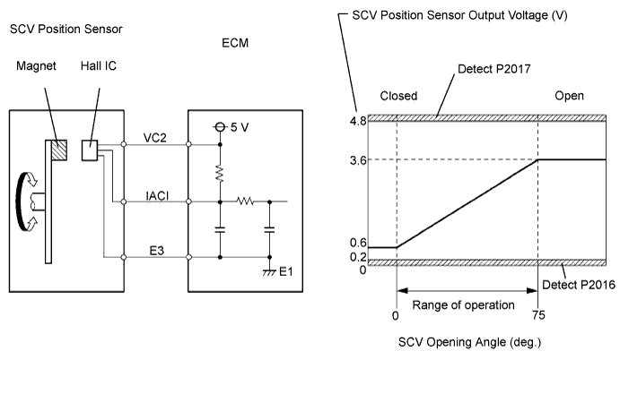
The Swirl Control Valve (SCV) position sensor is a non-contact type.The position sensor measures the opening angle of the SCV. The sensor is reliable and accurate, as it is electrically controlled by Hall elements.
The ECM's IACI terminal voltage increases in correlation with the opening angle of the SCV. When the SCV is fully closed, approximately 0.6 V is applied to the IACI terminal. When the SCV is fully open, approximately 3.6 V is applied to the IACI terminal.
When the output voltage of the IACI terminal deviates from the standard range, the ECM determines that a malfunction has occurred in the position sensor and outputs a DTC.

| DTC No. |
DTC Detection Condition |
Trouble Area |
| P2014 |
SCV position sensor output voltage flutters up and down beyond the normal operating range (Less than 0.2 V or more than 4.8 V for more than 0.5 seconds) (Open or short) |
|
| P2016 |
SCV position sensor output voltage is less than 0.2 V for more than 0.5 seconds (Short) |
Same as DTC No. P2014 |
| P2017 |
SCV position sensor output voltage is more than 4.8 V for more than 0.5 seconds (Open) |
Same as DTC No. P2014 |
- HINT:
- After confirming DTC P2014, P2016 or P2017, use the intelligent tester to confirm the SCV Angle Sensor (D4) (SCV position sensor output voltage) from Power train / Engine / Data List.
| SCV ANG SENS D4 |
Malfunction |
| 0.2 V or less |
|
| 4.8 V or more |
|
WIRING DIAGRAM
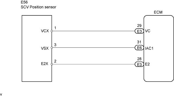
INSPECTION PROCEDURE
- HINT:
- If different DTCs that are related to a different system are output simultaneously while terminal E3 is used as a ground terminal, terminal E3 may be open.
- Read freeze frame data using the intelligent tester. Freeze frame data records the engine conditions when malfunctions are detected. When troubleshooting, freeze frame data can help determine if the vehicle was running or stopped, if the engine was warmed up or not, if the air-fuel ratio was lean or rich, and other data from the time the malfunction occurred (Click here).
- If different DTCs that are related to a different system are output simultaneously while terminal E3 is used as a ground terminal, terminal E3 may be open.
| 1. PERFORM ACTIVE TEST BY INTELLIGENT TESTER (OPERATE SCV) |

Connect the intelligent tester to the DLC3.
Turn the engine switch on (IG) and turn the tester ON.
Enter the following menus: Power train / Engine / Active Test / Control the SCV Duty Ratio.
Scroll the data list by the up or down button to display SCV ANG SENS D4 (SCV position sensor).
Check the output voltage of SCV ANG SENS D4 while the DC motor for SCV is driven from full closed to full open (or from full open to full closed) using the intelligent tester.
- Standard:
- The voltage output of SCV POSITION remains between 0.2 to 4.8 V while the DC motor for SCV is driven from -100 to 100 % (or from 100 to -100 %).
SCV DUTY RATIO
operation
SCV ANG SENS D4
(Normal)
Suspect failure area
- IACI circuit short
- VC2 circuit open
- VC2 and IACI circuit short-circuited
- IACI circuit open
- E3 circuit open
Sensor malfunction
-100 %
0.2 to 1.0 V
Remain less than 0.2 V
Remain more than 4.8 V
Sensor malfunction
100 %
3.2 to 4.8 V
Remain less than 0.2 V
Remain more than 4.8 V
- IACI circuit short
|
|
||||

| NG | |
 |
| 2. CHECK HARNESS AND CONNECTOR (SCV POSITION SENSOR - ECM) |
Disconnect the E3 and E6 ECM connectors.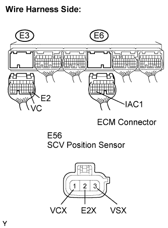
Disconnect the E56 SCV position sensor connector.
Measure the resistance of the wire harness side connector.
- Standard resistance (Check for open):
Tester Connection
Specified Condition
VC (E3-29) - VCX (E56-1)
Below 1 Ω
IAC1 (E6-31) - VSX (E56-3)
Below 1 Ω
E2 (E3-28) - E2X (E56-2)
Below 1 Ω
- Standard resistance (Check for short):
Tester Connection
Specified Condition
VC (E3-29) or VCX (E56-1) - Body ground
10 kΩ or higher
IAC1 (E6-31) or VSX (E56-3) - Body ground
10 kΩ or higher
E2 (E3-28) or E2X (E56-2) - Body ground
10 kΩ or higher
Reconnect the SCV position sensor connector.
Reconnect the ECM connector.
|
|
||||

| OK | |
|
| 3. INSPECT ECM (VC2 VOLTAGE) |
Disconnect the E56 SCV position sensor connector.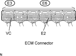
Turn the engine switch on (IG).
Measure the voltage of the E3 snf E6 ECM connector.
- Standard voltage:
Tester Connection
Specified Condition
VC (E3-29) - E2 (E3-28)
4.5 to 5.0 V
Reconnect the SCV position sensor connector.
|
|
||||
| OK | |
|
| 4. REPLACE INTAKE MANIFOLD |
| NEXT | |
|
| 5. CHECK WHETHER DTC OUTPUT RECURS (DTC P2014, P2016 AND/OR P2017 ARE OUTPUT AGAIN) |
Connect the intelligent tester to the DLC3.
Turn the engine switch on (IG) and turn the tester ON.
Clear DTCs.
Enter the following menus: Power train / Engine / DTC.
Read DTCs.
- Result:
Display (DTC Output)
Proceed to
P2014, P2016 and/or P2017 are output again
A
No output
B
|
|
||||
| A | ||
 |
||
| ||