B1214
Diagnostic trouble codes
DESCRIPTION
- When a +B short circuit or body ground short circuit is detected on the door system communication bus (BEAN), BEAN is disabled and a DTC is output.
| DTC No. |
DTC Detection Condition |
Trouble Area |
| B1214 |
Door system communication circuit and +B battery system short |
|
| B1215 |
Door system communication circuit and body ground short |
|
WIRING DIAGRAM
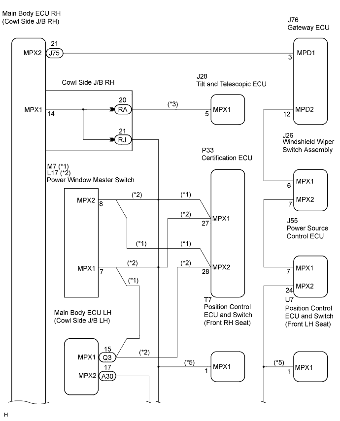

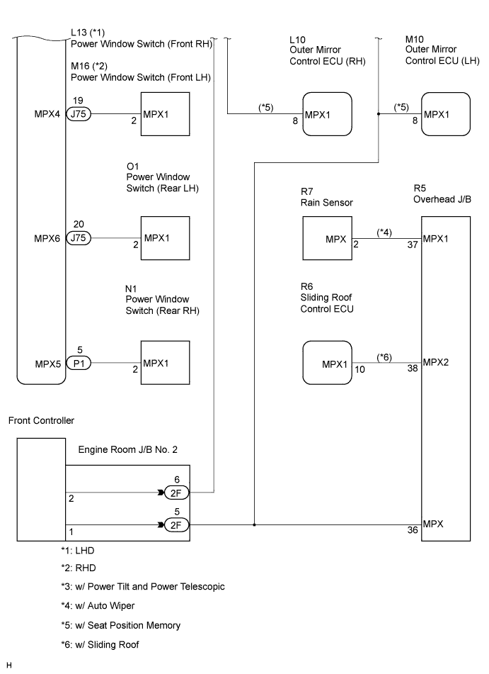
INSPECTION PROCEDURE
| 1. CHECK DIAGNOSTIC TROUBLE CODE (A ECU) |

Disconnect the A ECU connector and check for DTCs B1214 and B1215.
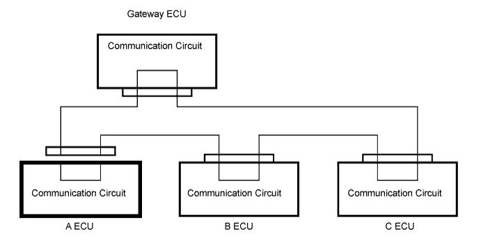
- OK:
- Neither DTC B1214 nor DTC B1215 is output.
- NOTICE:
- Reconnect the connector before starting the next check.
- HINT:
- The A ECU in the door system bus represents the main body ECU RH (cowl side J/B RH).
- If the result is as specified, the disconnected A ECU (main body ECU RH (cowl side J/B RH)) is malfunctioning.
- The A ECU in the door system bus represents the main body ECU RH (cowl side J/B RH).
|
|
||||

| NG | |
 |
| Go to step 3 |
| 2. CHECK DIAGNOSTIC TROUBLE CODE (B ECU) |
Disconnect the A ECU and B ECU connectors and check for DTCs B1214 and B1215.
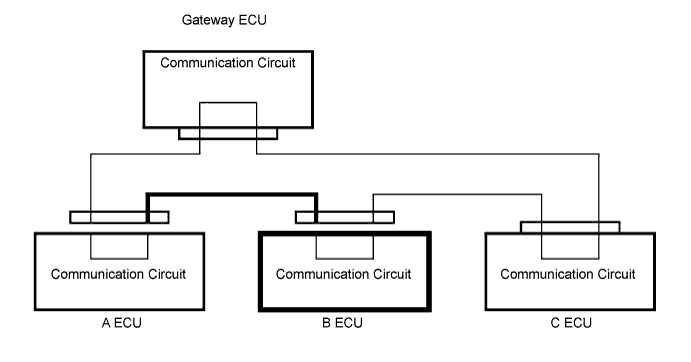
- OK:
- Neither DTC B1214 nor DTC B1215 is output.
- NOTICE:
- Disconnect the connectors one by one. Reconnect the connectors before starting the next check.
- HINT:
- Remove the B ECUs in the following order:
- Power window master switch
- Certification ECU
- Power source control ECU
- Main body ECU LH (cowl side J/B LH)
- Front controller
- Remove the B ECUs in the following order:
- If the result is as specified, the disconnected B ECU (one of the ECUs from the above list) or the wire harness between the A ECU and B ECU is malfunctioning.
- After the DTC is cleared, proceed to the next step.
- If the result is as specified, the disconnected B ECU (one of the ECUs from the above list) or the wire harness between the A ECU and B ECU is malfunctioning.
|
|
||||

| OK | |
|
| Go to step 4 |
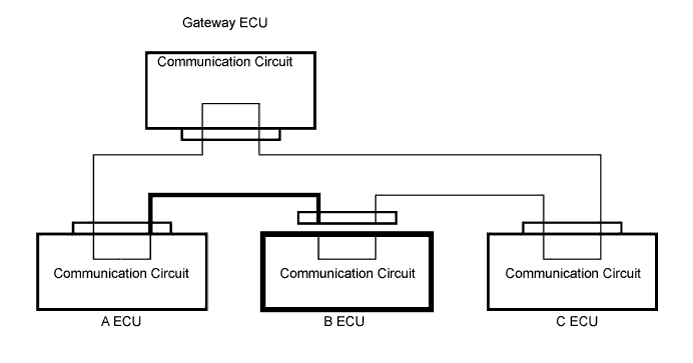
| 3. CHECK WIRE HARNESS BETWEEN A ECU AND B ECU |
Disconnect the B ECU connector and check for DTCs B1214 and B1215.
- OK:
- Neither DTC B1214 nor DTC B1215 is output.
- NOTICE:
- Reconnect the connector before starting the next check.
- HINT:
- If the result is as specified, the wire harness between the A ECU and B ECU is functioning normally but the disconnected B ECU is malfunctioning.
- If the result is as specified, the wire harness between the A ECU and B ECU is functioning normally but the disconnected B ECU is malfunctioning.
|
|
||||
| OK | ||
 |
||
| ||
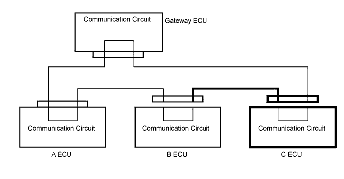
| 4. CHECK DIAGNOSTIC TROUBLE CODE (C ECU) |
Disconnect the B ECU and C ECU connectors and check for DTCs B1214 and B1215.
- OK:
- Neither DTC B1214 nor DTC B1215 is output.
- NOTICE:
- Disconnect the connectors one by one. Reconnect the connectors before starting the next check.
- HINT:
- The C ECU in the door system bus represents the windshield wiper switch.
- If the result is as specified, the disconnected C ECU (windshield wiper switch) or the wire harness between the B ECU and C ECU is malfunctioning.
- The C ECU in the door system bus represents the windshield wiper switch.
|
|
||||
| OK | |
|
| Go to step 6 |
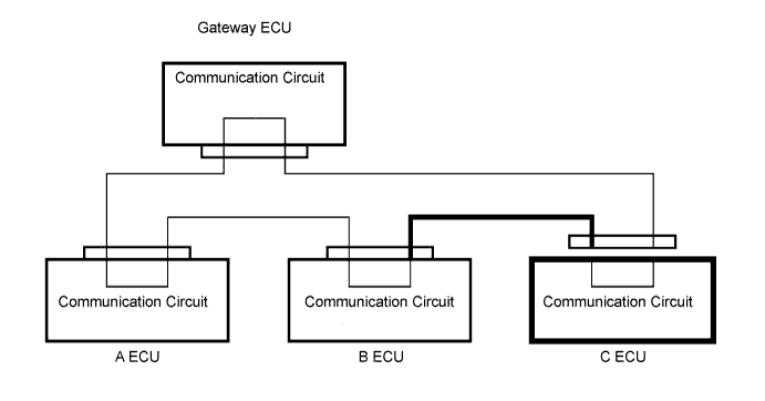
| 5. CHECK WIRE HARNESS BETWEEN B ECU AND C ECU |
Disconnect the C ECU connector and check for DTCs B1214 and B1215.
- OK:
- Neither DTC B1214 nor DTC B1215 is output.
- NOTICE:
- Reconnect the connector before starting the next check.
- HINT:
- If the result is as specified, the wire harness between the B ECU and C ECU is functioning normally but the disconnected C ECU is malfunctioning.
|
|
||||
| OK | ||
|
||
| ||
| 6. CHECK WIRE HARNESS BETWEEN GATEWAY ECU AND A ECU OR C ECU |
Check for a short-circuit in +B or body ground.
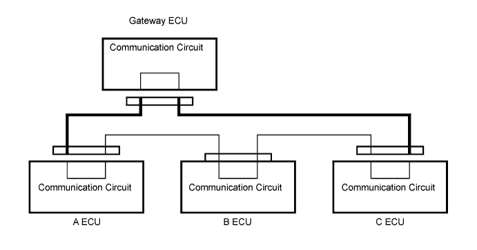
Disconnect the A ECU, C ECU and gateway ECU connectors.
Measure the voltage and resistance of the wire harness side connectors.
- Standard voltage:
Tester Connection
Specified Condition
A ECU connector/gateway ECU connector - Body ground
Below 1 V
C ECU connector/gateway ECU connector - Body ground
Below 1 V
- Standard resistance:
Tester Connection
Specified Condition
A ECU connector/gateway ECU connector - Body ground
10 kΩ or higher
C ECU connector/gateway ECU connector - Body ground
10 kΩ or higher
- HINT:
- The A ECU in the door system bus represents the main body ECU RH (cowl side J/B RH).
- The C ECU in the door system bus represents the windshield wiper switch.
- The A ECU in the door system bus represents the main body ECU RH (cowl side J/B RH).
|
|
||||
| OK | ||
|
||
| ||