VSC Warning Light Remains ON
Circuit diagnosis
DESCRIPTION
The skid control ECU is connected to the combination meter via CAN and multiplex communications.If the ECU stores DTC, the master caution indicator light will come on and the DTC will be displayed on the multi information display in the combination meter.
WIRING DIAGRAM
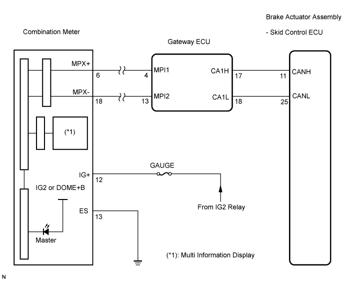

INSPECTION PROCEDURE
- NOTICE:
- When replacing the brake actuator assembly, perform zero point calibration (Click here).
| 1. CHECK CAN COMMUNICATION SYSTEM |

Check if the CAN communication system DTC is output (Click here for LHD, or Click here for RHD).
- Result:
Condition
Proceed to
DTC is not output
A
DTC is output
B
|
|
||||

| A | |
 |
| 2. CHECK MULTIPLEX COMMUNICATION SYSTEM |
Check if the multiplex communication system DTC is output (Click here).
- Result:
Condition
Proceed to
DTC is not output
A
DTC is output
B
|
|
||||
| A | |
|
| 3. CHECK IF SKID CONTROL ECU CONNECTOR IS SECURELY CONNECTED |
Check if the skid control ECU connector is securely connected.
- OK:
- The connector should be securely connected.
|
|
||||
| OK | |
|
| 4. CHECK BATTERY |
Check the battery voltage.
- Standard voltage:
- 11 to 14 V
|
|
||||
| OK | |
|
| 5. INSPECT COMBINATION METER ASSEMBLY |
Perform Active Test of the combination meter (meter CPU) using the intelligent tester (Click here).
- OK:
- The VSC warning (multi information display and master caution indicator light) light turns on or off in accordance with the intelligent tester.
- HINT:
- If troubleshooting has been carried out according to the Problem Symptoms Table, refer back to the table and proceed to the next step before replacing the part (Click here).
|
|
||||
| OK | ||
 |
||
| ||