C1267/67
Diagnostic trouble codes
DESCRIPTION
The brake pedal load sensing switch is turned on when the brake pedal is depressed with force exceeding a predetermined level.The skid control ECU detects if the brake pedal is depressed or not via this circuit.
| DTC No. |
DTC Detection Condition |
Trouble Area |
| C1267/67 |
When any of the following is detected:
|
|
WIRING DIAGRAM
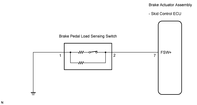

INSPECTION PROCEDURE
- NOTICE:
- When replacing the brake actuator assembly, perform zero point calibration (Click here).
- HINT:
- If C1249/49 is output, repair it before repairing C1267/67 based on the flow chart below.
| 1. READ VALUE OF INTELLIGENT TESTER (BRAKE PEDAL LOAD SENSING SWITCH) |

Connect the intelligent tester to the DLC3.
Start the engine.
Select the Data List mode on the intelligent tester.
ABS / VSC: Item (Display)
Measurement Item / Range (Display)
Normal Condition
Brake Pedal Load Sensing SW
Brake pedal load sensing switch / ON or OFF
ON : Depressed brake pedal
OFF : Released brake pedal
Read the value of the brake pedal load sensing switch displayed on the intelligent tester when depressing and releasing the brake pedal.
- OK:
Condition
Display
Brake pedal depressed
ON
Brake pedal released
OFF
|
|
||||

| NG | |
 |
| 2. INSPECT BRAKE PEDAL LOAD SENSING SWITCH |
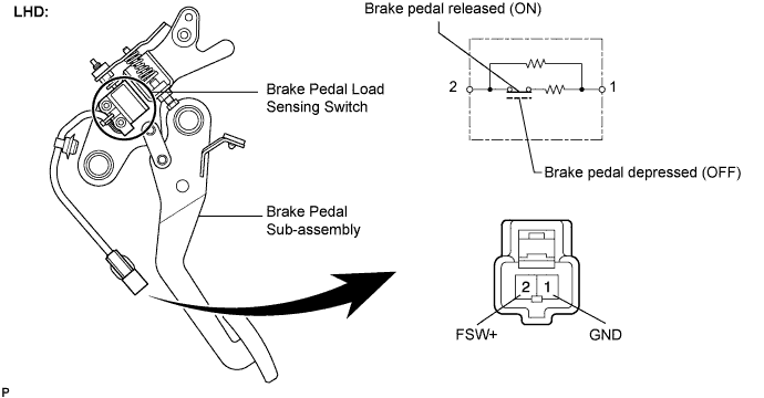
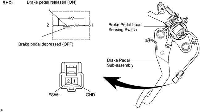
- NOTICE:
- Do not remove the brake pedal load sensing switch from the brake pedal sub-assembly.
- When there is a malfunction in the brake pedal load sensing switch, replace the brake pedal sub-assembly.
- Do not remove the brake pedal load sensing switch from the brake pedal sub-assembly.
Turn the engine switch off.
Disconnect the brake pedal load sensing switch connector.
Measure the resistance according to the value(s) in the table below.
- Standard resistance:
Tester Connection
Condition
Specified Condition
2 (FSW+) - 1 (GND)
Brake pedal depressed (OFF)
0.9 to 1.1 kΩ
2 (FSW+) - 1 (GND)
Brake pedal released (ON)
192 to 234 Ω
|
|
||||

| OK | |
|
| 3. CHECK HARNESS AND CONNECTOR (SKID CONTROL ECU - BRAKE PEDAL LOAD SENSING SWITCH) |
Disconnect the skid control ECU connector.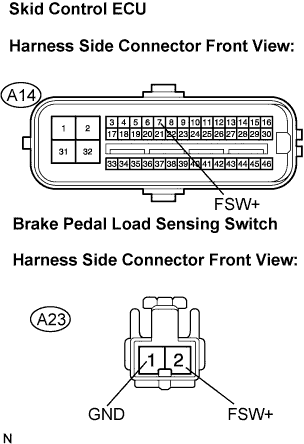
Measure the resistance according to the value(s) in the table below.
- Standard resistance:
Tester Connection
Condition
Specified Condition
A14-7 (FSW+) - A23-2 (FSW+)
Always
Below 1 Ω
A14-7 (FSW+) - Body ground
Always
10 kΩ or higher
A23-1 (GND) - Body ground
Always
Below 1 Ω
|
|
||||
| OK | |
|
| 4. RECONFIRM DTC |
Reconnect the skid control ECU connector and the brake pedal load sensing switch connector.
Clear the DTC (Click here).
Check if the same DTC is recorded (Click here).
- Result:
Condition
Proceed to
DTC (C1267/67) is not output
A
DTC (C1267/67) is output
B
|
|
||||
| A | ||
 |
||
| ||