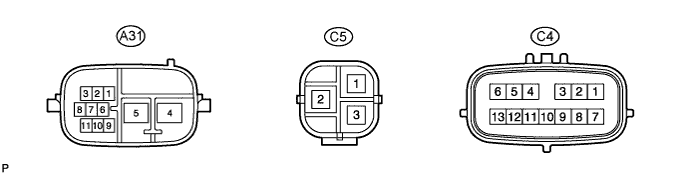
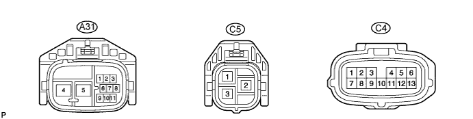
Terminal No. (Symbols)
|
Wiring Color
|
Terminal Description
|
A31-2 (CANH)
|
B
|
High-level CAN bus line
|
A31-3 (CANL)
|
R
|
Low-level CAN bus line
|
A31-4 (PIG)
|
R
|
Power source
|
A31-5 (PGND)
|
B
|
Power ground
|
A31-9 (IG)
|
B-Y
|
IG power source
|
C4-1 (RZG)
|
G
|
Rotation angle sensor power source circuit ground
|
C4-2 (SRZG)
|
BR
|
Rotation angle sensor shield ground
|
C4-3 (RZV)
|
B
|
Rotation angle sensor power source
|
C4-4 (TRQV)
|
W
|
Torque sensor power source
|
C4-6 (TQG1)
|
L-W
|
Torque sensor power source circuit ground
|
C4-7 (RZSN)
|
W
|
SIN phase input signal (Rotation angle sensor)
|
C4-8 (RZCS)
|
R
|
COS phase input signal (Rotation angle sensor)
|
C4-9 (INSN)
|
G-W
|
SIN phase input signal (torque sensor input shaft side)
|
C4-10 (INCS)
|
R-L
|
COS phase input signal (torque sensor input shaft side)
|
C4-11 (OUSN)
|
G-B
|
SIN phase input signal (torque sensor output shaft side)
|
C4-12 (OUCS)
|
Y-B
|
COS phase input signal (torque sensor output shaft side)
|
C4-13 (TQG2)
|
R-B
|
Torque sensor detection circuit ground
|
C5-1 (V)
|
W
|
V phase motor output
|
C5-2 (U)
|
B
|
U phase motor output
|
C5-3 (W)
|
R
|
W phase motor output
|