B2788
Diagnostic trouble codes
DESCRIPTION
The steering lock ECU receives power from the IG2 relay. When the voltage value indicated by the IG signal from the certification ECU equals to the voltage that is applied to the steering lock ECU, the steering will be unlocked. The steering lock ECU will not lock the steering when power from the IG2 relay is present (this prevents the steering from being locked while the vehicle is moving).| DTC No. |
DTC Detecting Condition |
Trouble Area |
| B2788 |
Different information is obtained from IG2 signals received directly from the IG2 circuit, and from IG2 signals sent via LIN communication for a period of 1 second. |
|
WIRING DIAGRAM
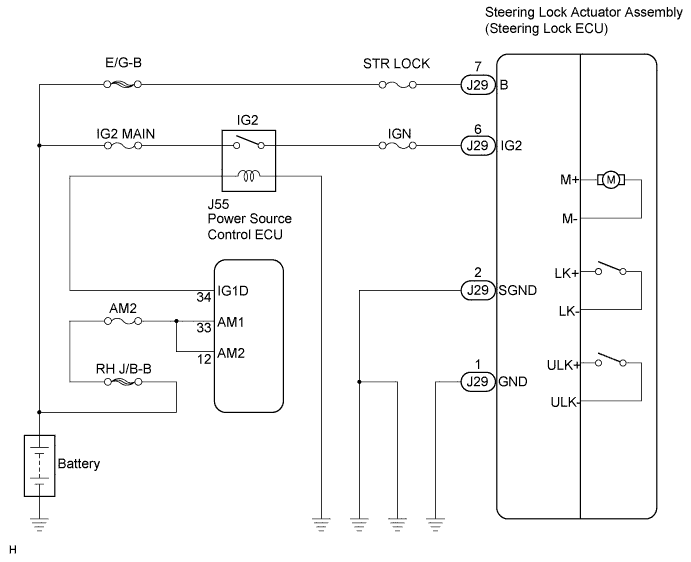

INSPECTION PROCEDURE
| 1. INSPECT IG2 RELAY |

Remove the IG2 relay from the engine room R/B No.2.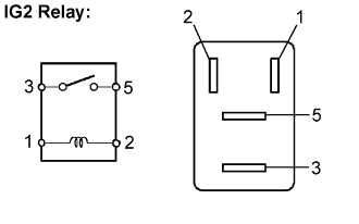
Measure the resistance according to the value(s) in the table below.
- Standard resistance:
Tester Connection
Specified Condition
3 - 5
10 kΩ or higher
3 - 5
Below 1 Ω
(when battery voltage is applied to terminals 1 and 2)
|
|
||||

| OK | |
 |
| 2. CHECK HARNESS AND CONNECTOR (STEERING LOCK ACTUATOR ASSEMBLY - BODY GROUND) |
Disconnect the J29 connector from the steering lock actuator assembly.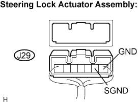
Measure the resistance according to the value(s) in the table below.
- Standard resistance:
Tester connection
(Symbols)
Condition
Specified condition
J29-1 (GND) - Body ground
Always
Below 1 Ω
J29-2 (SGND) - Body ground
Always
Below 1 Ω
|
|
||||
| OK | |
|
| 3. CHECK HARNESS AND CONNECTOR (STEERING LOCK ACTUATOR ASSEMBLY - BATTERY) |
Measure the voltage according to the value(s) in the table below.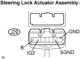
- Standard voltage:
Tester connection
(Symbols)
Condition
Specified condition
J29-6 (IG2) - J29-1 (GND)
Engine switch on (IG)
10 to 14 V
J29-6 (IG2) - J29-2 (SGND)
Engine switch on (IG)
10 to 14 V
Measure the resistance according to the value(s) in the table below.
- Standard resistance:
Tester connection
(Symbols)
Condition
Specified condition
*J29-6 (IG2) - J29-7 (B)
Engine switch off
10 kΩ or higher
|
|
||||
| NG | ||
 |
||
| ||