P0365
Diagnostic trouble codes
DESCRIPTION
The exhaust camshaft's Variable Valve Timing (VVT) sensor (G signal) consists of a magnet and MRE element.The exhaust camshaft has a sensor plate with 3 teeth on its outer circumference.
When the exhaust camshaft rotates, changes occur in the air gaps between the 3 teeth and pickup coil, which affects the magnet. As a result, the resistance of the MRE material fluctuates. The VVT sensor converts the exhaust camshaft rotation data to pulse signals, and uses the pulse signals to determine the camshaft angle, which it sends to the ECM. Then the ECM uses this data to control fuel injection time and injection timing. The crankshaft angle sensor plate has 34 teeth. The pickup coil generates 34 signals for each engine revolution. Based the G signal and actual crankshaft angle, the ECM detects the normal crankshaft angle. Also, based on the NE signal, the ECM detects the engine speed.
| DTC No. |
DTC Detection Condition |
Trouble Area |
| P0365 P0390 |
|
|
| P0367 P0392 |
Output voltage of VVT sensor 0.3 V or less for 5 seconds (1 trip detection logic) |
|
| P0368 P0393 |
Output voltage of VVT sensor 4.7 V or more for 5 seconds (1 trip detection logic) |
|
-
Reference: Inspection using an oscilloscope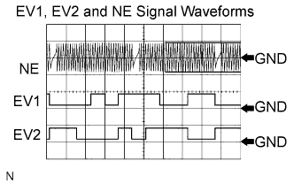

- HINT:
- The correct waveform is shown.
- EV1+ and EV2+ stand for the VVT sensor signal, and NE+ stands for the CKP sensor signal.
Item
Content
Terminal
NE+ - NE-
EV1+ - EV1-
EV2+ - EV2-
Equipment Setting
5 V/DIV.
20 ms./DIV.
Condition
Cranking or idling
- The correct waveform is shown.
WIRING DIAGRAM
Refer to DTC P0335 (Click here).INSPECTION PROCEDURE
Read freeze frame data using the intelligent tester. Freeze frame data records the engine conditions when malfunctions are detected. When troubleshooting, freeze frame data can help determine if the vehicle was running or stopped, if the engine was warmed up or not, if the air-fuel ratio was lean or rich, and other data from the time the malfunction occurred (Click here).| 1. CHECK ECM TERMINAL VOLTAGE |

Inspect the ECM using an oscilloscope.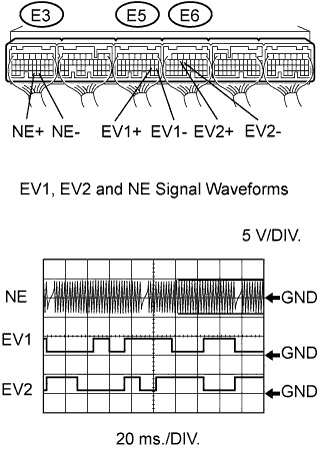
While the engine is idling, check the waveform between the terminals of the ECM connector.
- Standard:
Tester Connection
Specified Condition
EV1+ (E5-19) - EV1- (E5-18)
Correct waveform shown
EV2+ (E6-13) - EV2- (E6-12)
Correct waveform shown
NE+ (E3-32) - NE- (E3-31)
Correct waveform shown
|
|
||||

| NG | |
 |
| 2. CHECK HARNESS AND CONNECTOR (SENSOR POWER SOURCE) |
Disconnect the E25 or E34 VVT sensor connector.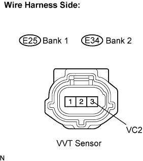
Measure the voltage of the wire harness side connector.
- Standard voltage:
Tester Connection
Specified Condition
VC2 (E25-3) - Body ground
4.5 to 5.0 V
VC2 (E34-3) - Body ground
4.5 to 5.0 V
Reconnect the VVT sensor connector.
|
|
||||
| OK | |
|
| 3. CHECK HARNESS AND CONNECTOR (VVT SENSOR - ECM) |
Disconnect the E25 or E34 VVT sensor connector.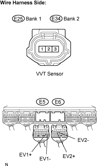
Disconnect the E5 or E6 ECM connector.
Measure the resistance of the wire harness side connector.
- Standard resistance (Check for open):
Tester Connection
Specified Condition
EX+ (E25-1) - EV1+ (E5-19)
Below 1 Ω
EX- (E25-2) - EV1- (E5-18)
Below 1 Ω
EX+ (E34-1) - EV2+ (E6-13)
Below 1 Ω
EX- (E34-2) - EV2- (E6-12)
Below 1 Ω
- Standard resistance (Check for short):
Tester Connection
Specified Condition
EX+ (E25-1) or EV1+ (E5-19) - Body ground
10 kΩ or higher
EX- (E25-2) or EV1- (E5-18) - Body ground
10 kΩ or higher
EX+ (E34-1) or EV2+ (E6-13) - Body ground
10 kΩ or higher
EX- (E34-2) or EV2- (E6-12) - Body ground
10 kΩ or higher
Reconnect the VVT sensor connector.
Reconnect the ECM connector.
|
|
||||
| OK | |
|
| 4. CHECK VVT SENSOR FOR EXHAUST CAMSHAFT (SENSOR INSTALLATION) |
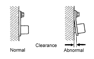 |
Check the VVT sensor installation.
- OK:
- Sensor is installed correctly.
|
|
||||
| OK | |
|
| 5. CHECK EXHAUST CAMSHAFT |
Check the teeth of the camshaft.
|
|
||||
| OK | ||
 |
||
| ||