Clutch Switch Circuit
Circuit diagnosis
DESCRIPTION
Clutch switch circuit inspection is necessary for M/T vehicles.When the clutch pedal is released, the ECM receives positive (+) battery voltage through the LH-IG fuse. While depressing the clutch pedal, the clutch switch sends a signal to terminal CLSW of the ECM. The ECM cancels cruise control drive when terminal CLSW receives the signal.
WIRING DIAGRAM
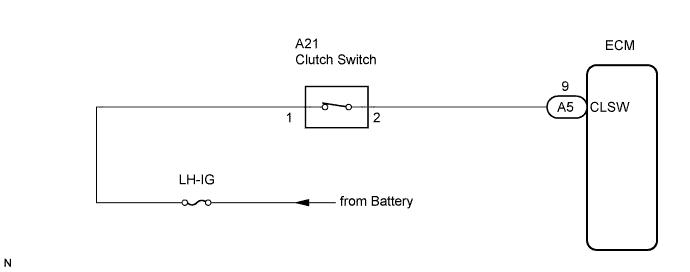

INSPECTION PROCEDURE
| 1. INSPECT ECM (CLSW TERMINAL) |

Disconnect the A5 connector from the ECM.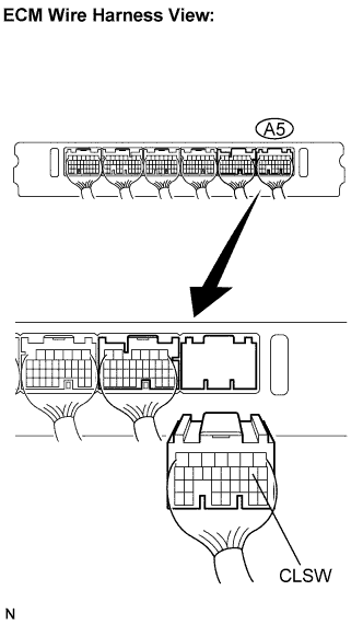
Turn the engine switch on (IG).
Measure the voltage according to the value(s) in the table below.
- Standard voltage:
Tester Connection
Condition
Specified Condition
A5-9 (CLSW) - Body ground
Clutch pedal depressed
Below 1 V
Clutch pedal released
10 to 14 V
|
|
||||

| NG | |
 |
| 2. INSPECT CLUTCH SWITCH |
Turn the engine switch off.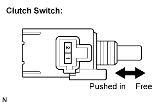
Disconnect the A21 connector from the clutch switch.
Remove the clutch switch (Click here).
Measure the resistance according to the value(s) in the table below.
- Standard resistance:
Tester Connection
Condition
Specified Condition
1 - 2
Switch pin free
(Clutch pedal depressed)
10 kΩ or higher
Switch pin pushed in
(Clutch pedal released)
Below 1 Ω
|
|
||||
| OK | |
|
| 3. CHECK HARNESS AND CONNECTOR (ECM - CLUTCH SWITCH) |
Measure the resistance according to the value(s) in the table below.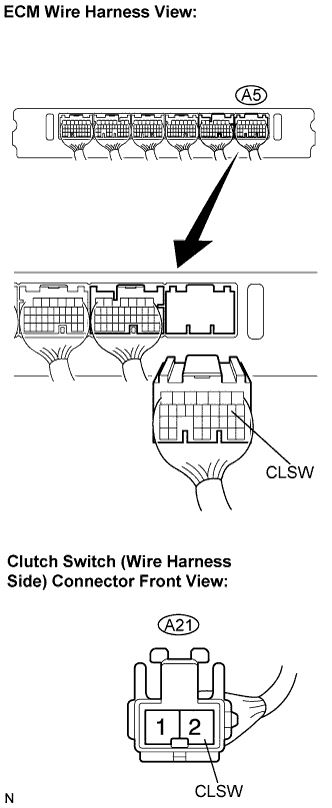
- Standard resistance:
Tester Connection
Condition
Specified Condition
A5-9 (CLSW) - A21-2
Always
Below 1 Ω
A5-9 (CLSW) - Body ground
Always
10 kΩ or higher
|
|
||||
| OK | ||
 |
||
| ||