U0235
Diagnostic trouble codes
DESCRIPTION
The millimeter wave radar sensor and distance control ECU (cruise control ECU) transmit the data for general vehicle control and diagnosis function along the communication line. The millimeter wave radar sensor transmits information about the vehicle in front to the distance control ECU (cruise control ECU).| DTC No. |
DTC Detection Condition |
Trouble Area |
| U0235 |
The ECM detects a communication error signal (from the millimeter wave radar sensor to the distance control ECU) for 0.15 sec. or more while the dynamic radar cruise control is in operation |
|
WIRING DIAGRAM
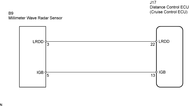

INSPECTION PROCEDURE
- NOTICE:
- When the distance control ECU is replaced with a new one, initialization must be performed (Click here).
- When the millimeter wave radar sensor is replaced with a new one, adjustment of the radar sensor beam axis must be performed (Click here).
- When the distance control ECU is replaced with a new one, initialization must be performed (Click here).
| 1. CHECK HARNESS AND CONNECTOR (DISTANCE CONTROL ECU - MILLIMETER WAVE RADAR SENSOR) |

Disconnect the distance control ECU and millimeter wave radar sensor connectors.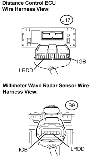
Measure the resistance according to the value(s) in the table below.
- Standard resistance:
Tester Connection
Condition
Specified Condition
J17-22 (LRDD) - B9-3 (LRDD)
Always
Below 1 Ω
J17-13 (IGB) - B9-5 (IGB)
Always
Below 1 Ω
J17-22 (LRDD) - Body ground
Always
10 kΩ or higher
J17-13 (IGB) - Body ground
Always
10 kΩ or higher
|
|
||||

| OK | |
 |
| 2. CHECK DISTANCE CONTROL ECU |
Disconnect the millimeter wave radar sensor connector.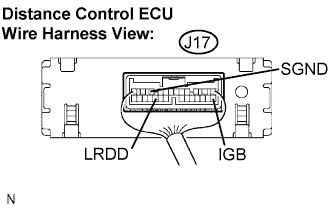
Measure the voltage according to the value(s) in the table below.
- Standard voltage:
Tester Connection
Condition
Specified Condition
J17-13 (IGB) - Body ground
Engine switch on (IG)
10 to 14 V
J17-22 (LRDD) - J17-10 (SGND)
Engine switch on (IG)
4.5 to 5.5 V
|
|
||||
| OK | |
|
| 3. CHECK MILLIMETER WAVE RADAR SENSOR |
Reconnect the millimeter wave radar sensor connector.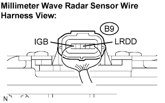
Measure the voltage according to the value(s) in the table below.
- Standard voltage:
Tester connection
Condition
Specified Condition
B9-5 (IGB) - Body ground
Engine switch on (IG)
10 to 14 V
Check the signal waveform between terminal LRDD (B9-3) of the millimeter wave radar sensor and body ground.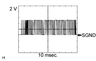
- OK:
- A waveform similar to that in the illustration on the left is output.
- HINT:
- Gauge set: 2 V/DIV., 10 msec./DIV.
- Condition: Engine switch on (IG)
- Gauge set: 2 V/DIV., 10 msec./DIV.
|
|
||||
| OK | ||
 |
||
| ||