Driver Side Door Key Lock and Unlock Switch Circuit
Circuit diagnosis
DESCRIPTION
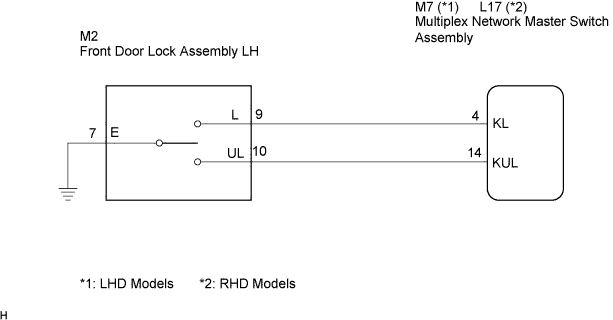
The driver's door key lock and unlock switch is built into the driver's door lock assembly.When the driver's door key cylinder is turned to lock all the doors by key, there is continuity between terminals L and E of the key lock and unlock switch. When the cylinder is turned to unlock the door(s), there is continuity between terminals UL and E.
Terminals KL and KUL of the multiplex network master switch assembly are connected to the door lock assembly, and door lock/unlock request signals (by key) are input to the multiplex network master switch assembly.
The multiplex network master switch assembly constantly applies voltage to terminal L of the driver's door lock assembly via terminal KL. When the driver's door key cylinder is turned to lock all the doors by key, current flows from terminal KL to terminal L. The multiplex network master switch assembly determines that this is door lock request signal input and sends a door lock signal to the main body ECU RH using multiplex communication.
The multiplex network master switch assembly also applies constant voltage to terminal UL of the door lock assembly via terminal KUL. When the door key cylinder is turned in the direction to unlock the door(s) by key, current flows from terminal KUL to terminal UL. The multiplex network master switch assembly determines that this is door unlock request signal input and sends a door unlock signal to the main body ECU RH using multiplex communication.
WIRING DIAGRAM

INSPECTION PROCEDURE
| 1. READ VALUE OF DATA LIST |

Check the DATA LIST to ensure proper function of the door unlock detection switch.
MASTER SW (Multiplex Network Master Switch Assembly): Item
Measurement Item /
Display (Range)
Normal Condition
Diagnostic Note
Door Key Linked Lock SW
Driver door lock/unlock switch lock signal (key-linked lock switch)
/ON or OFF
ON: Driver side door key cylinder is turned to LOCK
OFF: Driver side door key cylinder is not turned to LOCK
-
Door Key Linked Unlock SW
Driver door lock/unlock switch unlock signal (key-linked unlock switch)
/ON or OFF
ON: Driver side door key cylinder is turned to UNLOCK
OFF: Driver side door key cylinder is not turned to UNLOCK
-
- OK:
- The display is as specified in the normal condition column.
|
|
||||

| OK | ||
 |
||
| ||
| 2. INSPECT FRONT DOOR LOCK ASSEMBLY (DOOR KEY LOCK AND UNLOCK SWITCH) |
Remove the front door lock assembly.
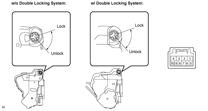
Measure the resistance according to the value(s) in the table below.
- Standard resistance:
Tester Connection
Condition
Specified Condition
7 - 9
ON (Door lock set to LOCK)
Below 1 Ω
7 - 9, 7 - 10
OFF (Free)
10 kΩ or higher
7 - 10
ON (Door lock set to UNLOCK)
Below 1 Ω
|
|
||||

| OK | |
 |
| 3. CHECK WIRE HARNESS (FRONT DOOR LOCK ASSEMBLY - MULTIPLEX NETWORK MASTER SWITCH) |
Disconnect the front door lock assembly connector.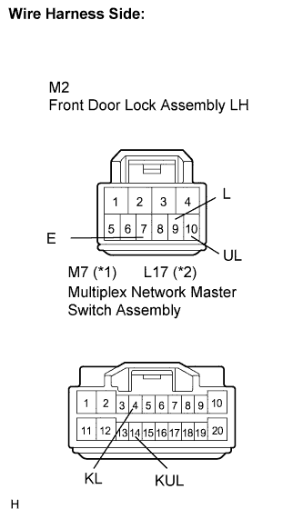
Disconnect the multiplex network master switch assembly connector.
Measure the resistance according to the value(s) in the table below.
- Standard resistance:
Tester Connection
(Symbols)
Condition
Specified Condition
M2-9 (L) - M7-4 (KL) (*1)
Always
Below 1 Ω
M2-10 (UL) - M7-14 (KUL) (*1)
Always
Below 1 Ω
M2-9 (L) - L17-4 (KL) (*2)
Always
Below 1 Ω
M2-10 (UL) - L17-14 (KUL) (*2)
Always
Below 1 Ω
M2-7 (E) - Body ground
Always
Below 1 Ω
M2-9 (L) - Body ground
Always
10 kΩ or higher
M2-10 (UL) - Body ground
Always
10 kΩ or higher
|
|
||||
| OK | ||
|
||
| ||