Driver Side Power Window Motor Circuit
Circuit diagnosis
DESCRIPTION
This circuit transmits signals from the multiplex network master switch to the power window regulator motor.WIRING DIAGRAM
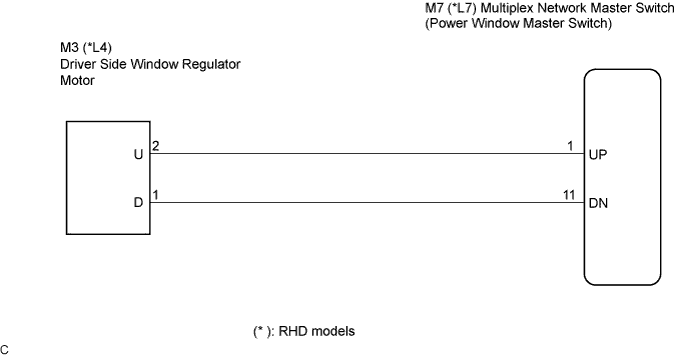

INSPECTION PROCEDURE
| 1. INSPECT POWER WINDOW REGULATOR MOTOR |

Remove the power window motor.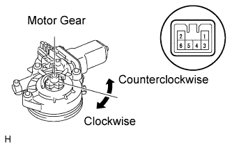
Apply battery voltage to the motor connector according to the table below.
- NOTICE:
- Do not apply battery voltage to any terminals except terminals 1 and 2.
- Standard:
Measurement Condition
Specified Condition
Battery positive (+) → Terminal 2 (U)
Battery negative (-) → Terminal 1 (D)
Motor gear rotates clockwise
Battery positive (+) → Terminal 1 (D)
Battery negative (-) → Terminal 2 (U)
Motor gear rotates counterclockwise
|
|
||||

| OK | |
 |
| 2. CHECK WIRE HARNESS (WINDOW REGULATOR MOTOR - MULTIPLEX NETWORK MASTER SWITCH) |
Disconnect the M7 (L17) and M3 (L4) connectors.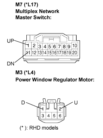
Measure the resistance according to the value(s) in the table below.
- Resistance:
- LHD models:
Tester Connection
Condition
Specified Condition
M7-1 (UP) - M3-2 (U)
Always
Below 1 Ω
M7-11 (DN) - M3-1 (D)
Always
Below 1 Ω
M7-1 (UP) - Body ground
Always
10 kΩ or higher
M7-11 (DN) - Body ground
Always
10 kΩ or higher
- RHD models:
Tester Connection
Condition
Specified Condition
L17-1 (UP) - L4-2 (U)
Always
Below 1 Ω
L17-11 (DN) - L4-1 (D)
Always
Below 1 Ω
L17-1 (UP) - Body ground
Always
10 kΩ or higher
L17-11 (DN) - Body ground
Always
10 kΩ or higher
|
|
||||
| OK | ||
 |
||
| ||