TERMINALS OF ECU
System information
| CHECK OUTER MIRROR CONTROL ECU LH |
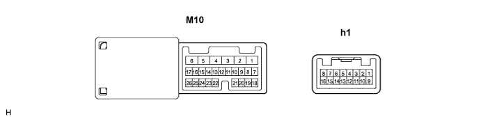

Disconnect the M10 connector.
Measure the voltage and resistance according to the value(s) in the table below.
- Voltage:
Symbols (Terminal No.)
Wiring Color
Terminal Description
Condition
Specified Condition
SIG (M10-3) - Body ground
B - Body ground
Ignition power supply
Engine switch OFF → ON (IG)
0 V → 10 to 14 V
CPUB (M10-4) - Body ground
G - Body ground
+B power supply
Always
10 to 14 V
BDR (M10-6) - Body ground
L - Body ground
+B power supply
Always
10 to 14 V
- Resistance:
Symbols (Terminal No.)
Wiring Color
Terminal Description
Condition
Specified Condition
GND (M10-1) - Body ground
W-B - Body ground
Ground
Always
Below 1 Ω
Reconnect the M10 connector.
Measure the voltage according to the value(s) in the table below.
- Voltage:
Symbols (Terminal No.)
Wiring Color
Terminal Description
Condition
Specified Condition
MV (h1-1) - Body ground
W - Body ground
Outer mirror switch signal (Up or Right)
Engine switch on (IG), Left/Right adjustment switch L side, Mirror switch OFF→ UP or Right
0 V → 10 to 14 V
VC (h1-5) - Body ground
R-W - Body ground
Power source for mirror position sensor
Engine switch OFF → ON (IG)
0 V → 0 to 5 V
VSSR (h-6) - Body ground
V - Body ground
Vertical direction position signal
Engine switch on (IG), Left/Right adjustment switch L side, Mirror switch uppermost position → lowermost position
0 V → 1 to 3 V
MH (h1-9) - Body ground
R - Body ground
Outer mirror switch signal (Left or Down)
Engine switch on (IG), Left/Right adjustment switch L side, Mirror switch OFF→ LEFT or DOWN
0 V → 10 to 14 V
M+ (h1-10) - Body ground
B - Body ground
Outer mirror switch signal (Right or Down)
Engine switch on (IG), Left/Right adjustment switch L side, Mirror switch OFF→ RIGHT or DOWN
0 V → 10 to 14 V
HSSR (h1-13) - Body ground
LG - Body ground
Horizontal direction position signal
Engine switch on (IG), Left/Right adjustment switch L side, Mirror switch innermost position → outermost position
0 V → 1 to 3 V
| CHECK OUTER MIRROR CONTROL ECU RH |
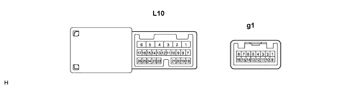
Disconnect the L10 connector.
Measure the voltage and resistance according to the value(s) in the table below.
- Voltage:
Symbols (Terminal No.)
Wiring Color
Terminal Description
Condition
Specified Condition
SIG (L10-3) - Body ground
B - Body ground
Ignition power supply
Engine switch OFF → ON (IG)
0 V → 10 to 14 V
CPUB (L10-4) - Body ground
G - Body ground
+B power supply
Always
10 to 14 V
BDR (L10-6) - Body ground
L - Body ground
+B power supply
Always
10 to 14 V
- Resistance:
Symbols (Terminal No.)
Wiring Color
Terminal Description
Condition
Specified Condition
GND (L10-1) - Body ground
W-B - Body ground
Ground
Always
Below 1 Ω
Reconnect the L10 connector.
Measure the voltage according to the value(s) in the table below.
- Voltage:
Symbols (Terminal No.)
Wiring Color
Terminal Description
Condition
Specified Condition
MV (g1-1) - Body ground
W - Body ground
Outer mirror switch signal (Up or Right)
Engine switch on (IG), Left/Right adjustment switch R side, Mirror switch OFF→ UP or Right
0 V → 10 to 14 V
VC (g1-5) - Body ground
R-W - Body ground
Power source for mirror position sensor
Engine switch OFF → ON (IG)
0 V → 0 to 5 V
VSSR (g-6) - Body ground
V - Body ground
Vertical direction position signal
Engine switch on (IG), Left/Right adjustment switch R side, Mirror switch uppermost position → lowermost position
0 V → 1 to 3V
MH (g1-9) - Body ground
R - Body ground
Outer mirror switch signal (Left or Down)
Engine switch on (IG), Left/Right adjustment switch R side, Mirror switch OFF→ LEFT or DOWN
0 V → 10 to 14 V
M+ (g1-10) - Body ground
B - Body ground
Outer mirror switch signal (Right or Down)
Engine switch on (IG), Left/Right adjustment switch R side, Mirror switch OFF→ RIGHT or DOWN
0 V → 10 to 14 V
HSSR (g1-13) - Body ground
LG - Body ground
Horizontal direction position signal
Engine switch on (IG), Left/Right adjustment switch R side, Mirror switch innermost position → outermost position
0 V → 1 to 3 V