TERMINALS OF ECU
System information
| A/C AMPLIFIER ASSEMBLY |


Measure the voltage and resistance according to the value(s) in the table below.
- Voltage:
- LHD models:
Symbols (Terminal No.)
Wiring Color
Terminal Description
Condition
Specified Condition
SW-5 (J59-2) - Body ground
LG - Body ground
Input climate control signal (Driver side)
Always
10 to 14 V
SW-4 (J59-3) - Body ground
R - Body ground
Input climate control signal (Passenger side)
Always
10 to 14 V
S5-4 (J59-7) - Body ground
BR - Body ground
GND
Engine switch on (IG)
4 to 6 V
SG-4 (J59-10) - Body ground
GR - Body ground
Power supply
Always
10 to 14 V
- RHD models:
Symbols (Terminal No.)
Wiring Color
Terminal Description
Condition
Specified Condition
SW-5 (J59-3) - Body ground
LG - Body ground
Input climate control signal (Driver side)
Always
10 to 14 V
SW-4 (J59-2) - Body ground
R - Body ground
Input climate control signal (Passenger side)
Always
10 to 14 V
S5-4 (J59-7) - Body ground
BR - Body ground
GND
Engine switch on (IG)
4 to 6 V
SG-4 (J59-10) - Body ground
GR - Body ground
Power supply
Always
10 to 14 V
- Standard:
- LHD models:
Symbols (Terminal No.)
Wiring Color
Terminal Description
Condition
Specified Condition
ROUT (J59-8) - Body ground
W - Body ground
Output climate control signal (Front RH side)
Engine switch on (IG)
Pulse generation
LOUT (J59-16) - Body ground
Y - Body ground
Output climate control signal (Front LH side)
Engine switch on (IG)
Pulse generation
- RHD models:
Symbols (Terminal No.)
Wiring Color
Terminal Description
Condition
Specified Condition
ROUT (J59-16) - Body ground
W - Body ground
Output climate control signal (Front RH side)
Engine switch on (IG)
Pulse generation
LOUT (J59-8) - Body ground
Y - Body ground
Output climate control signal (Front LH side)
Engine switch on (IG)
Pulse generation
Waveform (Reference): Using an oscilloscope: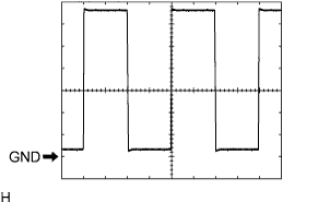
Item
Condition
Tool setting
2 V/DIV., 500 μsec/DIV.,
Vehicle condition
Turn the engine switch on (IG)