B1208
Diagnostic trouble codes
DESCRIPTION
- This DTC is detected when communication between the outer mirror control ECU (passenger side outer mirror ECU) and gateway ECU stops for more than 10 seconds.
| DTC No. |
DTC Detection Condition |
Trouble Area |
| B1208 |
Outer mirror control ECU (passenger side) communication stops |
|
WIRING DIAGRAM
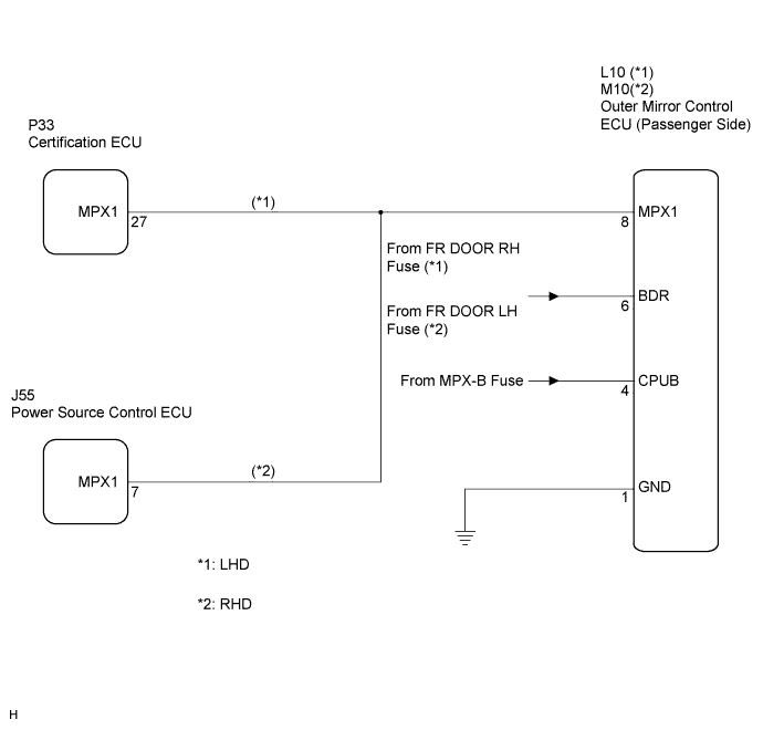

INSPECTION PROCEDURE
- HINT:
- When "+B of GND short malfunction of communication bus" DTCs (B1214 and B1215) are detected at the same time as "communication stop" DTC B1208, repair the "+B or GND short malfunction of communication bus" DTCs first.
| 1. INSPECT FUSE (FR DOOR RH (LHD), FR DOOR LH (RHD), MPX-B) |

Remove the FR DOOR RH fuse from the main body ECU RH (cowl side J/B RH) (for LHD).
Remove the FR DOOR LH fuse from the main body ECU LH (cowl side J/B LH) (for RHD).
Remove the MPX-B fuse from the engine room J/B No. 1.
Measure the resistance of the fuse.
- Standard resistance:
- Below 1 Ω
|
|
||||

| OK | |
 |
| 2. CHECK WIRE HARNESS (OUTER MIRROR CONTROL ECU - BATTERY AND BODY GROUND) |
Disconnect the L10 ECU connector (for LHD).
Disconnect the M10 ECU connector (for RHD).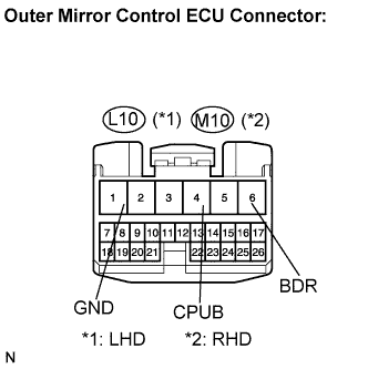
Measure the voltage and resistance of the wire harness side connector.
- Standard voltage:
Tester Connection
Condition
Specified Condition
*1BDR (L10-6) - Body ground
*2BDR (M10-6) - Body ground
Always
10 to 14 V
*1CPUB (L10-4) - Body ground
*2CPUB (M10-4) - Body ground
Always
10 to 14 V
- Standard resistance:
Tester Connection
Specified Condition
*1GND (L10-1) - Body ground
*2GND (M10-1) - Body ground
Below 1 Ω
- HINT:
- *1: LHD
- *2: RHD
- *1: LHD
|
|
||||
| OK | |
|
| 3. CHECK RESISTANCE OF COMMUNICATION LINE |
Disconnect the L10 and P33 ECU connectors (for LHD).
Disconnect the M10 and P34 ECU connector (for RHD).
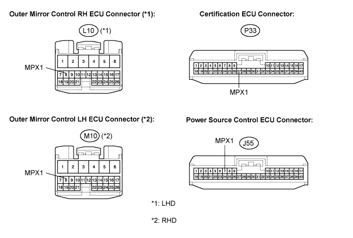
Measure the resistance between the specified terminals on the wire harness side connectors.
- Standard resistance:
Tester Connection
Specified Condition
*1MPX1 (L10-8) - MPX1 (P33-27)
*2MPX1 (M10-8) - MPX1 (J55-7)
Below 1 Ω
*1MPX1 (L10-8) - Body ground
*2MPX1 (M10-8) - Body ground
10 kΩ or higher
- HINT:
- *1: LHD
- *2: RHD
- *1: LHD
|
|
||||
| OK | ||
 |
||
| ||