Rear Double Lock Position Switch LH Circuit
Circuit diagnosis
DESCRIPTION
The rear left side door double lock position switch is built into the rear left side door lock assembly. The switch turns on when the rear left side door double lock is set and turns off when the double lock is released.The double door lock ECU is connected to the rear left side door lock assembly via terminal DLPL and rear left side door double lock set/released state signals are input to the ECU.
The double door lock ECU applies voltage to terminal DLSR of the double lock position switch via terminal DLPL. When the switch is on (there is continuity between the switch terminals), a set state signal is input to the ECU. When the switch is off (there is no continuity between the switch terminals), a release state signal is input.
The double door lock ECU sends rear left side door double lock set/released state signal to the main body ECU RH using multiplex communication.
WIRING DIAGRAM
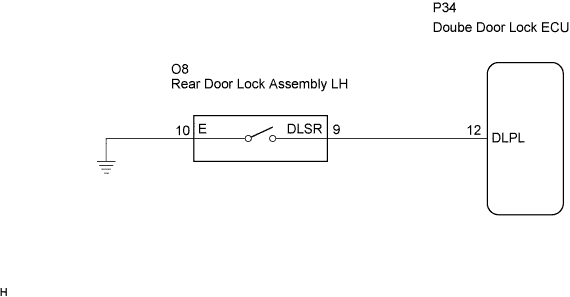

INSPECTION PROCEDURE
| 1. INSPECT REAR DOOR LOCK ASSEMBLY LH (DOUBLE LOCK POSITION SWITCH) |

Remove the rear door lock assembly LH.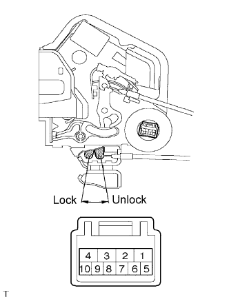
Apply battery voltage and set the door lock motor to the lock position.
- OK:
Measurement Condition
Specified Condition
Battery positive (+) →Terminal 2
Battery negative (-) →Terminal 1
Lock
Apply battery voltage to the door lock and check operation of the double lock motor.
- OK:
Measurement Condition
Specified Condition
Battery positive (+) →Terminal 4
Battery negative (-) →Terminal 3
Double Locking System is set
Battery positive (+) →Terminal 3
Battery negative (-) →Terminal 4
Double Locking System is unset
Measure the resistance according to the value(s) in the table below.
- Standard resistance:
Tester Connection
Double Lock Position
Specified Condition
9 - 10
Set
Below 1 Ω
9 - 10
Unset
10 kΩ or higher
|
|
||||

| OK | |
 |
| 2. CHECK WIRE HARNESS (REAR DOOR LOCK ASSEMBLY LH - DOUBLE DOOR LOCK ECU) |
Disconnect the rear door lock assembly LH connector.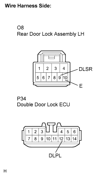
Disconnect the double door lock ECU connector.
Measure the resistance according to the value(s) in the table below.
- Standard resistance:
Tester Connection
(Symbols)
Condition
Specified Condition
O8-9 (DLSR) - P34-12 (DLPL)
Always
Below 1 Ω
O8-9 (DLSR) - Body ground
Always
10 kΩ or higher
O8-10 (E) - Body ground
Always
Below 1 Ω
|
|
||||
| OK | ||
 |
||
| ||