Speaker Circuit
Circuit diagnosis
DESCRIPTION
The sound signal that has been amplified by the stereo component amplifier is sent to the speakers from the stereo component amplifier through this circuit.If there is a short in this circuit, the stereo component amplifier detects it and stops output to the speakers.
Thus, sound cannot be heard from the speakers even if there is no malfunction in the stereo component amplifier or speakers.
WIRING DIAGRAM
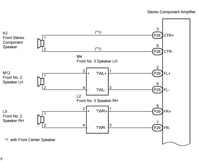

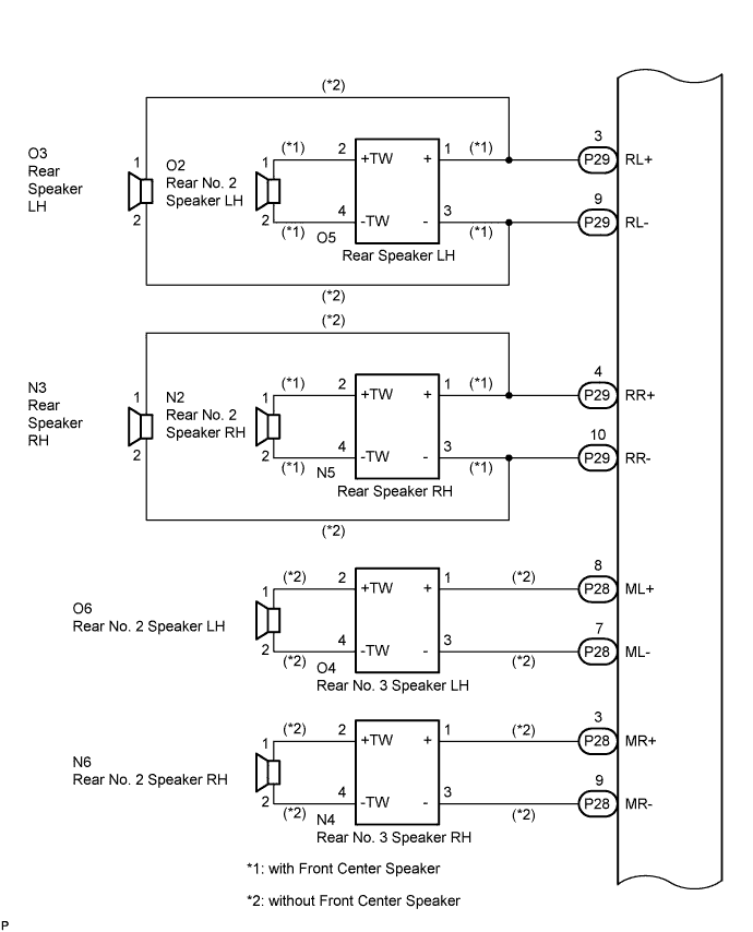
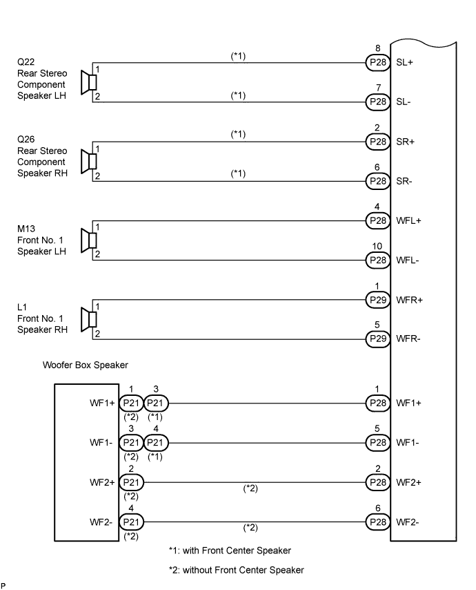
INSPECTION PROCEDURE
| 1. CHECK HARNESS AND CONNECTOR |

Disconnect the connectors shown in the illustration from the stereo component amplifier and speakers.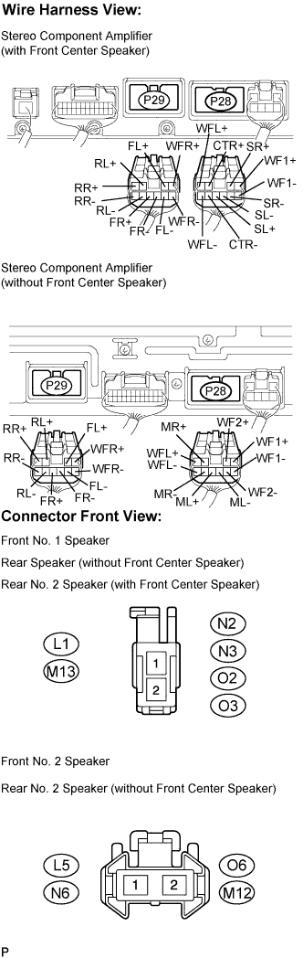
with Front Center Speaker:Measure the resistance between the front stereo component speaker and the stereo component amplifier to check for an open circuit in the wire harness.
- Standard resistance:
- Below 1 Ω
Measure the resistance between each of the front No. 3 speakers and the stereo component amplifier to check for an open circuit in the wire harness.
- Standard resistance:
- Below 1 Ω
Measure the resistance between each of the front No. 2 speakers and the front No. 3 speakers to check for an open circuit in the wire harness.
- Standard resistance:
- Below 1 Ω
without Front Center Speaker:Measure the resistance between each of the rear speakers and the stereo component amplifier to check for an open circuit in the wire harness.
- Standard resistance:
- Below 1 Ω
with Front Center Speaker:Measure the resistance between each of the rear speakers and the stereo component amplifier to check for an open circuit in the wire harness.
- Standard resistance:
- Below 1 Ω
without Front Center Speaker:Measure the resistance between each of the rear No. 3 speakers and the stereo component amplifier to check for an open circuit in the wire harness.
- Standard resistance:
- Below 1 Ω
without Front Center Speaker:Measure the resistance between each of the rear No. 2 speakers and the rear No. 3 speakers to check for an open circuit in the wire harness.
- Standard resistance:
- Below 1 Ω
with Front Center Speaker:Measure the resistance between each of the rear No. 2 speakers and the rear speakers to check for an open circuit in the wire harness.
- Standard resistance:
- Below 1 Ω
with Front Center Speaker:Measure the resistance between each of the rear stereo component speakers and the stereo component amplifier to check for an open circuit in the wire harness.
- Standard resistance:
- Below 1 Ω
Measure the resistance between each of the front No. 1 speakers and the stereo component amplifier to check for an open circuit in the wire harness.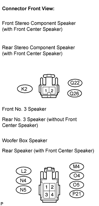
- Standard resistance:
- Below 1 Ω
Measure the resistance between the woofer box speaker and the stereo component amplifier to check for an open circuit in the wire harness.
- Standard resistance:
- Below 1 Ω
Measure the resistance between each speaker and body ground to check for a short circuit in the wire harness.
- Standard resistance:
- 10 kΩ or higher
|
|
||||

| OK | |
 |
| 2. INSPECT FRONT NO. 1 SPEAKER |
Resistance check.
Measure the resistance between the terminals of the speaker.
- Standard resistance:
- with Front Center Speaker:
- 6 to 10 Ω
- without Front Center Speaker:
- Approximately 4 Ω
- HINT:
- Perform the above inspection on both LH and RH sides.
|
|
||||
| OK | |
|
| 3. INSPECT FRONT NO. 2 SPEAKER |
Check that the malfunction disappears when another speaker in good condition is installed.
- Standard:
- Malfunction disappears.
- HINT:
- Connect all the connectors to the front No. 2 speakers.
- When there is a possibility that either the right or left front speaker is detective, inspect by interchanging the right one with the left one.
- Perform the above inspection on both LH and RH sides.
- Connect all the connectors to the front No. 2 speakers.
|
|
||||
| NG | |
|
| 4. INSPECT FRONT NO. 3 SPEAKER |
Check that the malfunction disappears when another speaker in good condition is installed.
- Standard:
- Malfunction disappears.
- HINT:
- Connect all the connectors to the front speakers.
- When there is a possibility that either the right or left front speaker is defective, inspect by interchanging the right one with the left one.
- Perform the above inspection on both LH and RH sides.
- Connect all the connectors to the front speakers.
|
|
||||
| NG | |
|
| 5. INSPECT REAR NO. 2 SPEAKER |
Check that the malfunction disappears when another speaker in good condition is installed.
- Standard:
- Malfunction disappears.
- HINT:
- Connect all the connectors to the rear No. 2 speakers.
- When there is a possibility that either the right or left rear speaker is detective, inspect by interchanging the right one with the left one.
- Perform the above inspection on both LH and RH sides.
- Connect all the connectors to the rear No. 2 speakers.
|
|
||||
| NG | |
|
| 6. CONFIRM MODEL |
- Result:
Result
Proceed to
with Front Center Speaker
A
without Front Center Speaker
B
|
|
||||

| A | |
|
| 7. INSPECT REAR SPEAKER |
Check that the malfunction disappears when another speaker in good condition is installed.
- Standard:
- Malfunction disappears.
- HINT:
- Connect all the connectors to the rear speakers.
- When there is a possibility that either the right or left rear speaker is detective, inspect by interchanging the right one with the left one.
- Perform the above inspection on both LH and RH sides.
- Connect all the connectors to the rear speakers.
|
|
||||
| NG | |
|
| 8. INSPECT REAR STEREO COMPONENT SPEAKER |
Check that the malfunction disappears when another speaker in good condition is installed.
- OK:
- Malfunction disappears.
- HINT:
- Connect all the connectors to the rear stereo component speakers.
- When there is a possibility that either the right or left rear speaker is detective, inspect by interchanging the right one with the left one.
- Perform the above inspection on both LH and RH sides.
- Connect all the connectors to the rear stereo component speakers.
|
|
||||
| NG | |
|
| 9. INSPECT FRONT STEREO COMPONENT SPEAKER |
Resistance check.
Measure the resistance between the terminals of the speaker.
- Standard resistance:
- 7 to 9 Ω
|
|
||||
| OK | |
|
| 10. INSPECT WOOFER BOX SPEAKER |
Resistance check.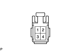
Measure the resistance according to the value(s) in the table below.
- NOTICE:
- The speaker should not be removed for checking.
- Standard resistance:
Tester connection
Condition
Specified condition
3 - 4
Always
7 to 8.6 Ω
|
|
||||
| OK | ||
 |
||
| ||
| 11. INSPECT REAR NO. 3 SPEAKER |
Check that the malfunction disappears when another speaker in good condition is installed.
- Standard:
- Malfunction disappears.
- HINT:
- Connect all the connectors to the rear No. 3 speakers.
- When there is a possibility that either the right or left rear No. 3 speaker is detective, inspect by interchanging the right one with the left one.
- Perform the above inspection of both LH or RH sides.
- Connect all the connectors to the rear No. 3 speakers.
|
|
||||
| NG | |
|
| 12. INSPECT REAR SPEAKER |
Resistance check.
Measure the resistance according to the value(s) in the table below.
- Standard resistance:
- Approximately 4 Ω
- HINT:
- Perform the above inspection on both LH and RH sides.
|
|
||||
| OK | |
|
| 13. INSPECT WOOFER BOX SPEAKER |
Resistance check.
Measure the resistance according to the value(s) in the table below.
- NOTICE:
- The speaker should not be removed for checking.
- Standard resistance:
Tester connection
Condition
Specified condition
1 - 3
Always
Approximately 2 Ω
2 - 4
Always
Approximately 2 Ω
|
|
||||
| OK | ||
|
||
| ||